


The Servo Deploy Model Rocket Altimeter you build yourself!
Have you ever wanted to use an electronic altimeter to find out how high your rockets fly, but you have found that the commercially available altimeter products are too expensive? U.S. Water Rockets proudly presents the LaunchPad AlTImeter, a very low cost model rocketry peak recording altimeter with optional apogee detect output and servo motor control connection. With this "Do it yourself" project, you can save close to 80% or more of the cost compared to commercially available altimeter systems. Anyone can make this project by following the free instructions we provide and the free firmware package available on our USWaterRockets.com website.

We are also planning on getting this design approved for actual rocketry competitions, and wish to work with groups like the WRA2.org and NPL.co.uk to that goal.
Table of contents:
Please click a links below to jump to a section of the documentation. If you are new to barometric altimeters or have only used simple toy altimeters in the past, you should take the time to carefully read the documentation. There are many simple things you can do to improve the accuracy of your altimeter data that are discussed in this documentation.Introduction:
The LaunchPad AlTImeter is a low cost, high quality "Do It Yourself" model rocket altimeter that has optional parachute deploy outputs which you can easily make yourself for far less cost than commercially available altimeters on the market that have only a fraction of the performance!
Our experience in building word record setting high altitude water rockets using many of the major commercially available altimeter brands has given us the background experience needed to create an altimeter that is uniquely suited for use with all forms of model rockets, including water rockets. The LaunchPad AlTImeter is the first rocket altimeter specifically designed to address the needs of both Pyro and Water Rockets.
The LaunchPad AlTImeter can be assembled as a simple altimeter, or it can be built with an optional servo for parachute recovery. It also has a digital output that signals apogee detect for use with external recovery hardware.
What it does:
The primary function of the LaunchPad AlTImeter is to report how high your model rocket flew. A secondary function allows you to connect optional Servo Motors or Ignition systems to deploy a parachute at apogee. Knowing how high your rocket flew after each flight can help you tune your rockets for better performance, and the ability to trigger a parachute at apogee results in safer and more reliable recovery.How it works:
LaunchPad AlTImeter is installed in the payload compartment of a model rocket and measures the current altitude of the rocket over 100 times a second. The specialized software running in the onboard MSP430 microcontroller processes any changes in altitude over time to detect key events in the rocket flight where specific actions take place, like detecting the liftoff, or deploying a parachute at apogee.Altitude is measured with a micromechanical barometric pressure sensor which senses the weight of the atmosphere pressing down from above. The determination of altitude this way is possible because the higher you are in the atmosphere, the less air there is above to press down
The LaunchPad AlTImeter uses the US Standard Atmosphere model 1976 (NASA) to convert the measured pressure into altitude.
Quick Start Guide:
This section will help you resolve the most common problems that people encounter with the LaunchPad AlTImeter.From time to time you may encounter an issue that you do not understand. Use this troubleshooting guide to help resolve problems.
If you are already familiar with model rocket altimeters, or you are simply an all-knowing genius, you can skip many of the details of this documentation and follow these steps to
get up and running fast!
- Go right to the Parts List and Assembly Tutorial Sections of this document to build your LaunchPad AlTImeter
- If you are using the Parachute Deploy features, read the Parachute Deploy section and User Configuration sections.
- Install the LaunchPad AlTImeter in your rocket, leaving a vent hole to allow the outside air pressure to reach the sensor.
- Arm the launch detection system by pressing and holding in S2 for 5 seconds, and wait 30 seconds for the arming delay to expire.
- You can now launch your rocket.
- After landing, you can read out the apogee altitude on the red and green LEDs or listening to the optional buzzer beeping.
For technical support, please use the LaunchPad AlTImeter technical support forum.
[Back to Table of Contents]
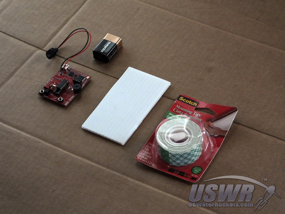
Parts List:
To assemble a LaunchPad AlTImeter, a number of components are required.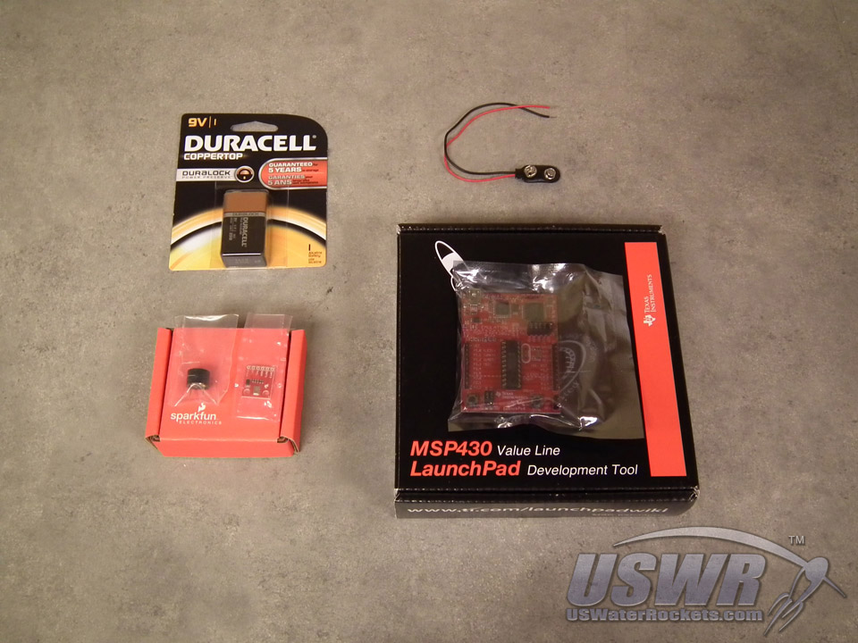
Parts needed for basic Altimeter:
| Component | Source | Part Number |
| MSP430 LaunchPad | estore.ti.com | MSP-EXP430G2 |
| Pressure Sensor Breakout | SparkFun | SEN-11084 |
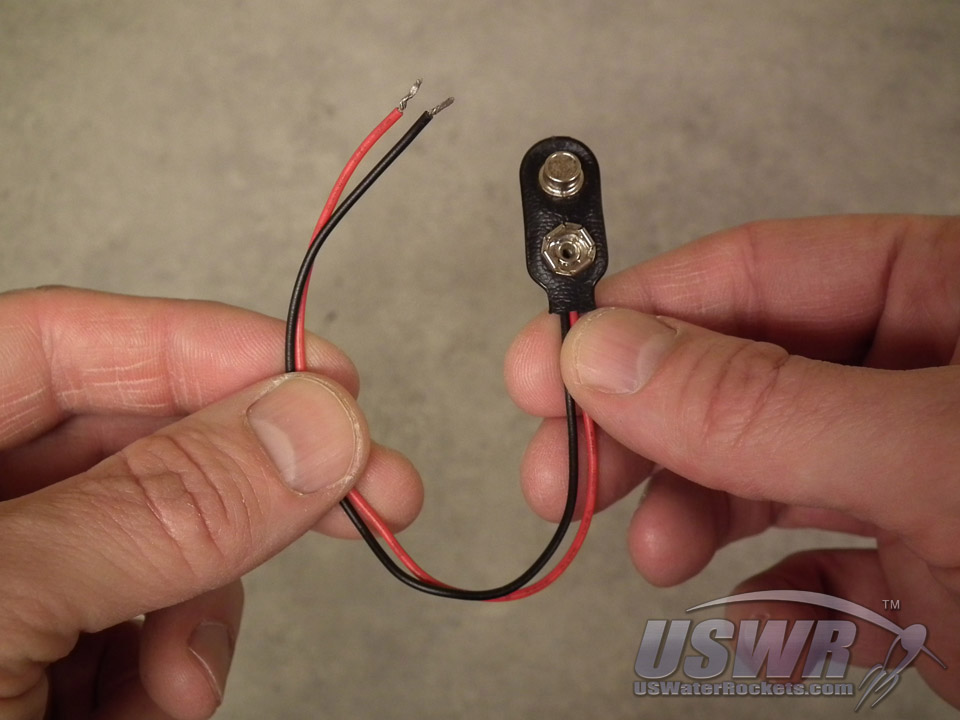
| 9V Battery Connector** | SparkFun | PRT-00091 |
| 9V Battery** | SparkFun | PRT-10218 |
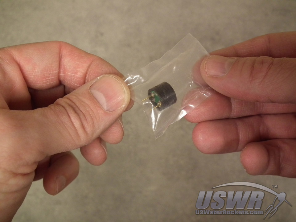
| Audio Transducer | SparkFun | COM-07950 |

Optional Parts needed for Servo Deploy:
| Component | Source | Part Number |
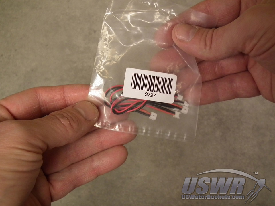
| Mini Plug for Micro Battery | HobbyKing | HK9727 |
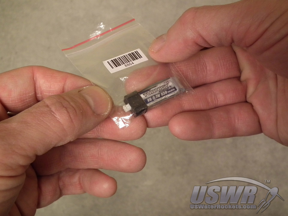
| 138mAh Lithium Polymer Cell | HobbyKing | BAT13810C |
| HXT900 9g Micro Servo | HobbyKing | HXT900 |
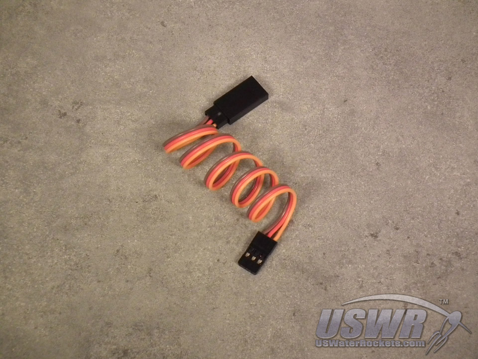
| Jr-Type Servo Extension Lead** | HobbyKing | AM1043-10-32 |

Assembly:

Tools Needed to build the LaunchPad AlTImeter:
- Wire Cutter
- Wire Stripper
- Solder
- Soldering Iron
- Hobby Knife
Be aware that there are some exceptions to the assembly that you will need to follow if you plan on using a Servo recovery system with the LaunchPad AlTImeter. Exceptions will be clearly marked. If you choose not to use a servo, you can ignore the exceptions.
Note that there are multiple versions of the MSP430 LaunchPad board which have been manufactured over the years, and the instructions will vary slightly from one board version to another. These instructions will note any different procedures you need to follow for different MSP430 LaunchPad versions.

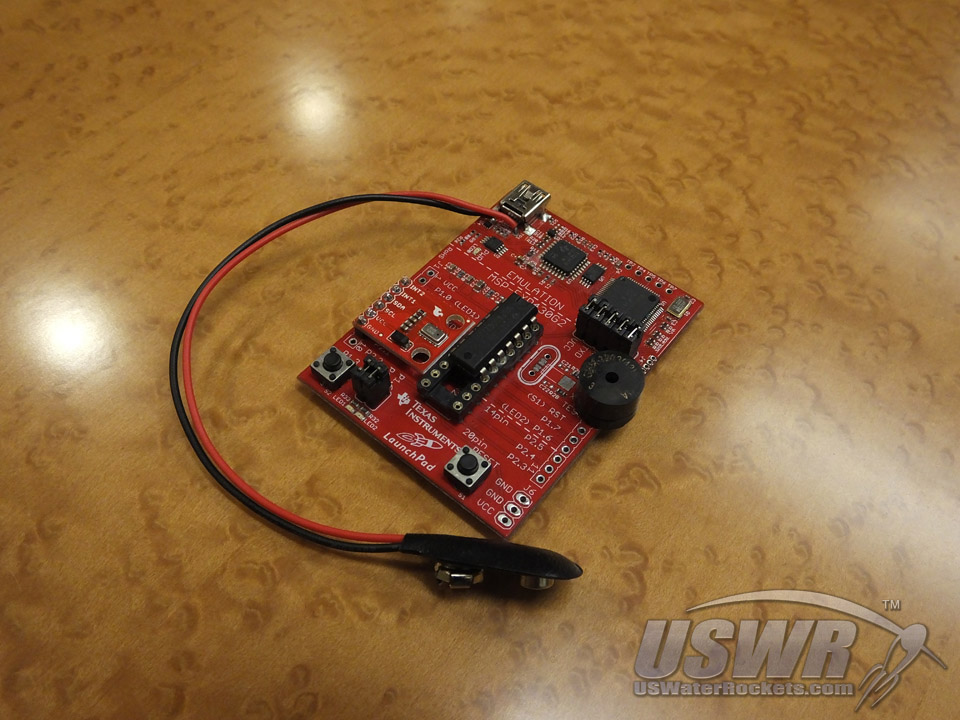
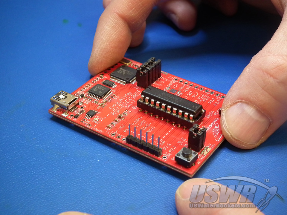
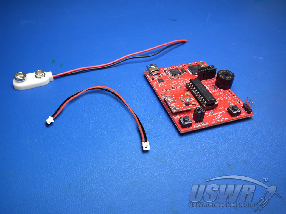
Step 1: Unboxing the Texas Instruments MSP430 LaunchPad Evaluation Kit:
Open up the box containing the Texas Instruments MSP430 LaunchPad Evaluation Kit, and remove the main board and the Mini USB cable. These are the only items in the box which you will need for this project. Save the rest of the parts (especially the spare microcontroller integrated circuit in a safe place, as we have plans for those which you may want to follow in the future.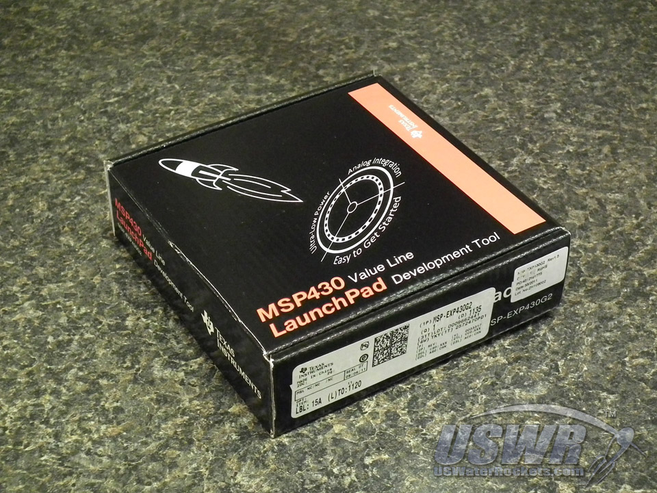

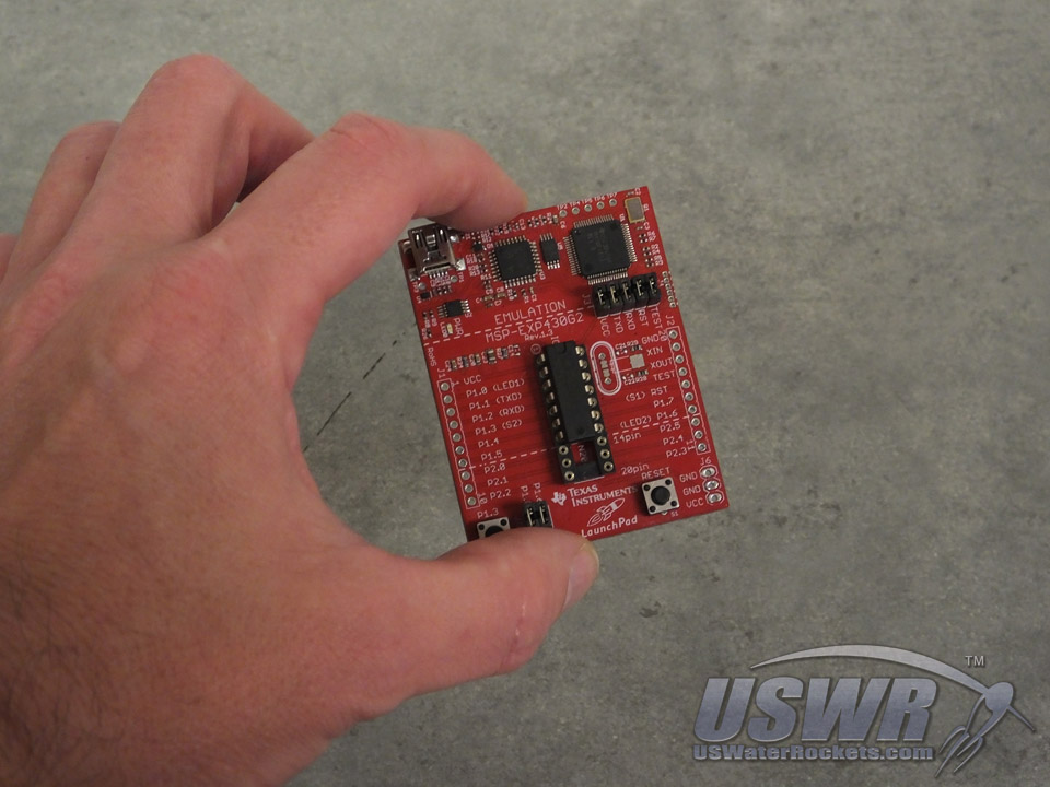
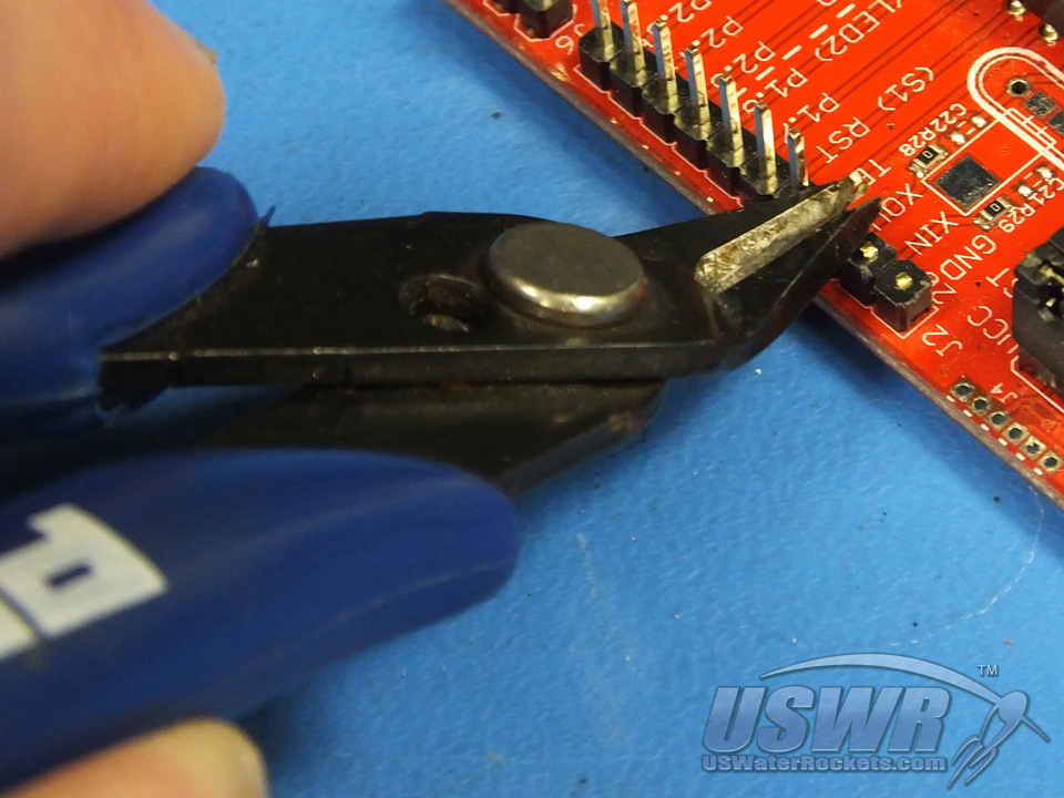
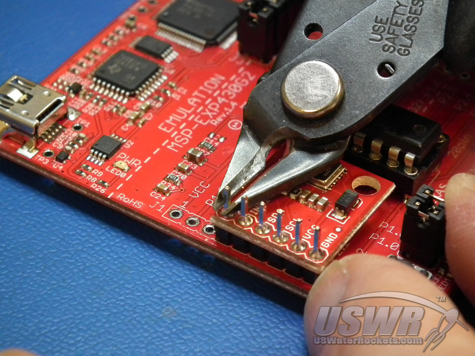
Step 2: Prepare the Male Header pins used on the MSP430 LaunchPad:
The MSP430 LaunchPad comes with 20 male pins in 2 rows of 10. Older model boards shipped with the pins included in a small package in the box, not installed. Only 6 pins are needed for this project, soldered in connector J1 holes 4 through 9. Clip off or de-solder and remove any unused header pins (or install the required pins, if they were shipped separately in the box).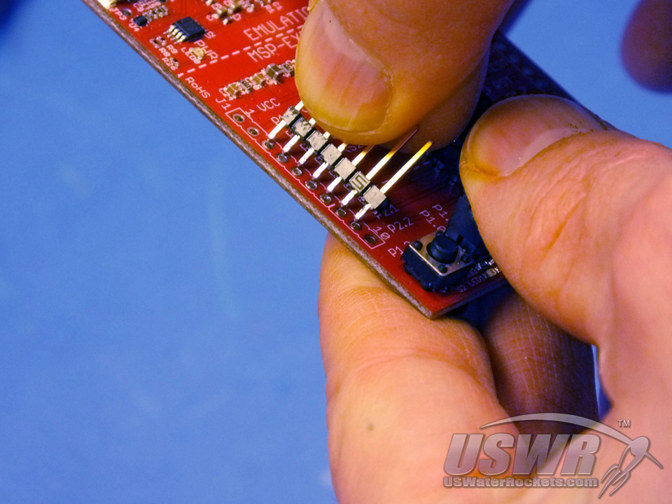
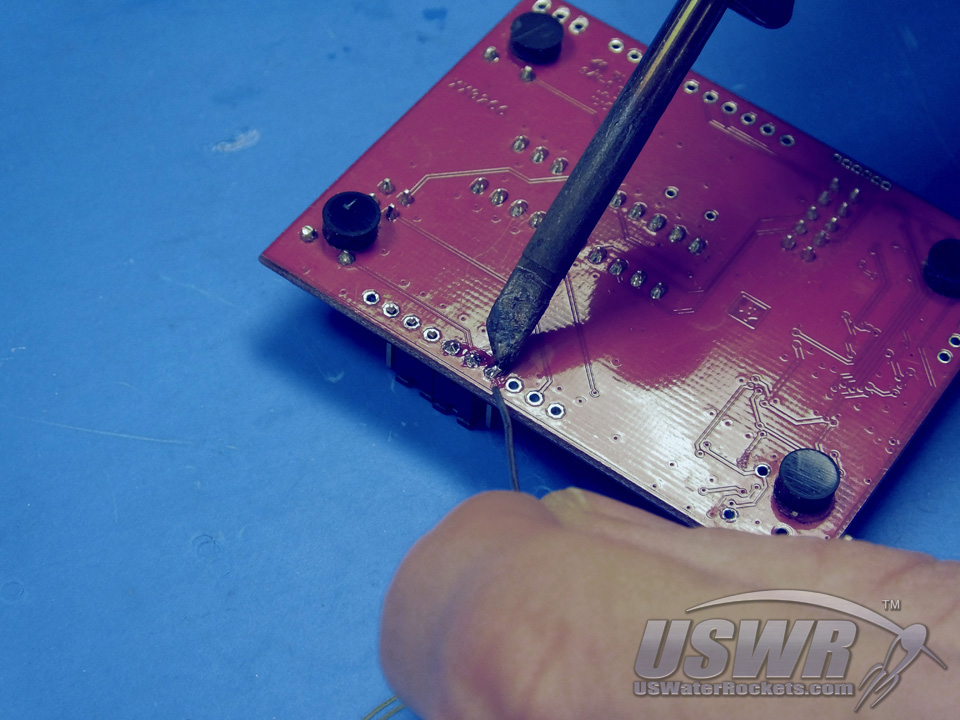
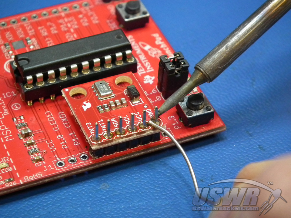
Step 3: Solder the barometric pressure sensor breakout board to the MSP430 LaunchPad:
You must solder the pressure sensor breakout board to J1 pins 4 to 9 in the position shown in the assembly photos. Make sure that the sensor board is oriented as shown before you solder each pin to the male header pin.When you have finished soldering the pressure sensor breakout board in place, you can trim off the excess portion of the male header pins protruding through the board.


Step 4: Add jumper wires if you are using the 14-pin MSP430 chip:
Some MSP430 LaunchPads ship with a CPU that has 14 legs, and others ship with a 20 leg chip. If you have a chip with 14 legs, you need to install 2 additional wires. One wire connects pin #8 of J1 header to pin #1 of J1. The second wire connects pin #9 of J1 to the bottom of S2. If you do not have wire on hand, you can take a small portion of the battery lead for this purpose.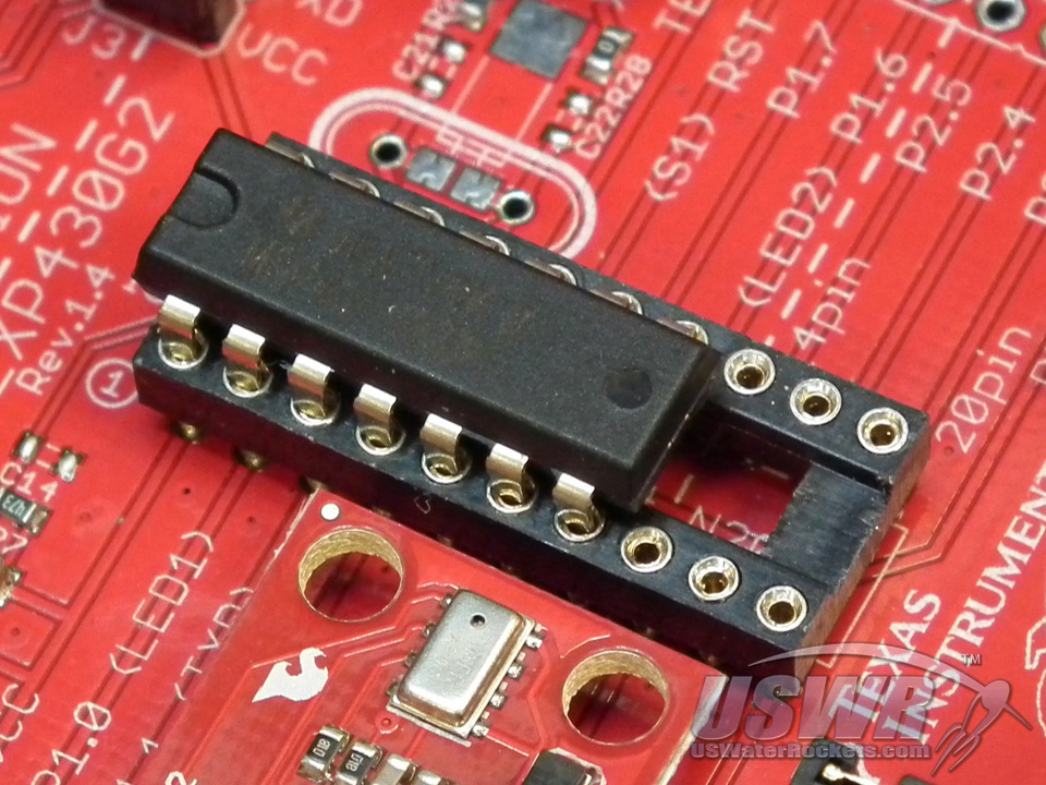
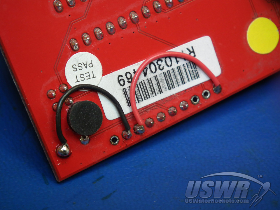
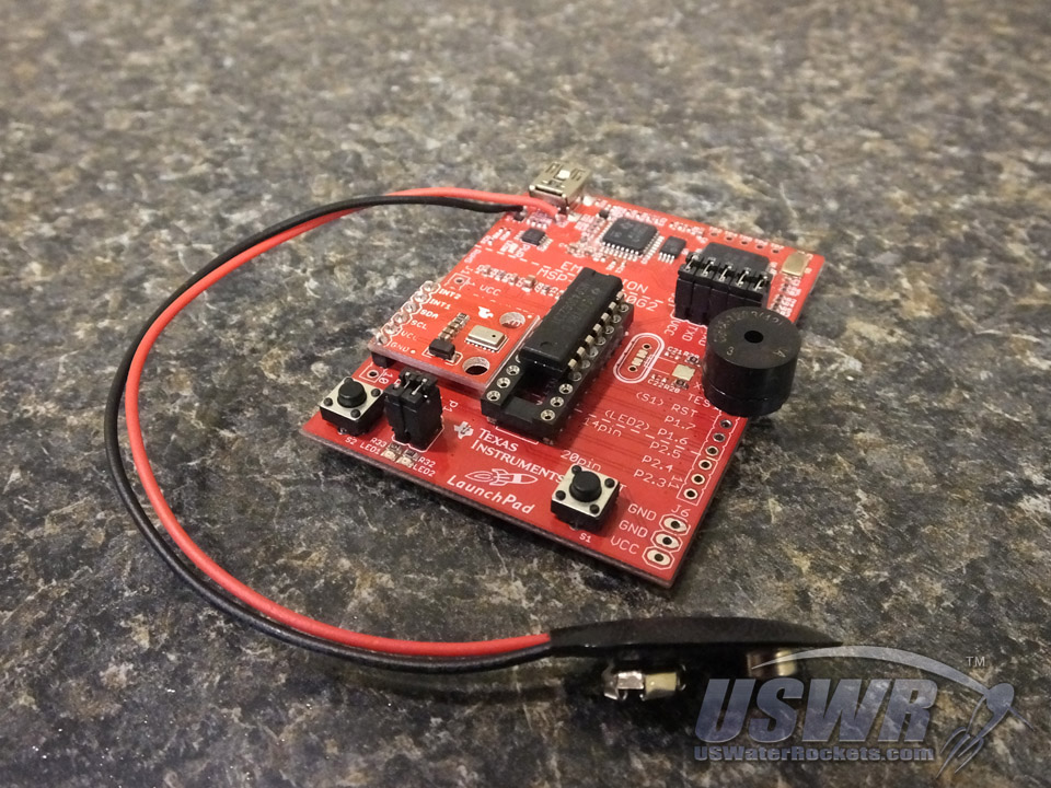
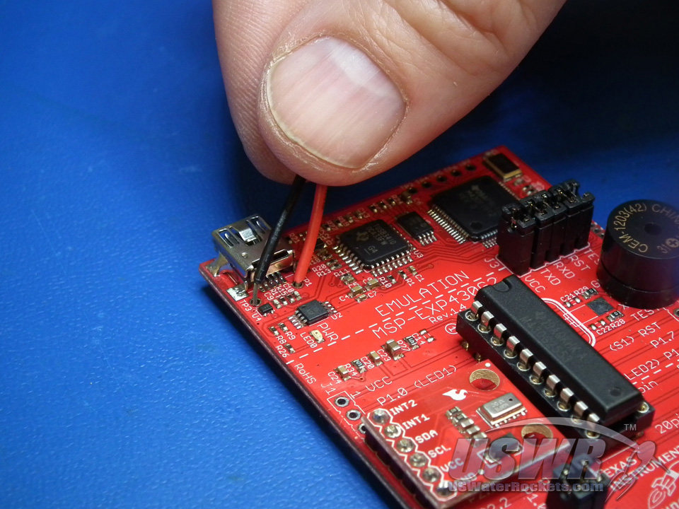
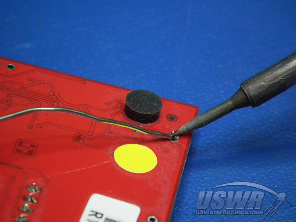
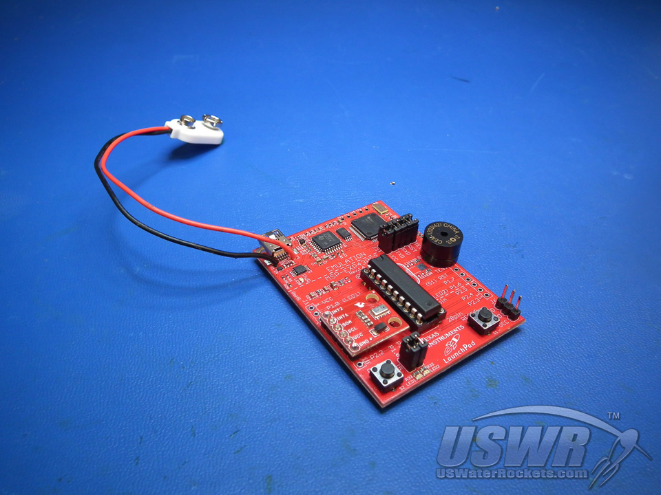
Step 5: Solder the battery connector to the locations shown in the accompanying photos.
If you do not plan to use the optional servo deploy, you can use a 9V battery and battery clip. If you are going to add the optional servo deploy, then you should install the Mini Plug for Micro Battery.Solder the Red and Black wires in the holes as shown. CAUTION: Do not swap the colors in the holes because this will destroy your MSP430 LaunchPad.

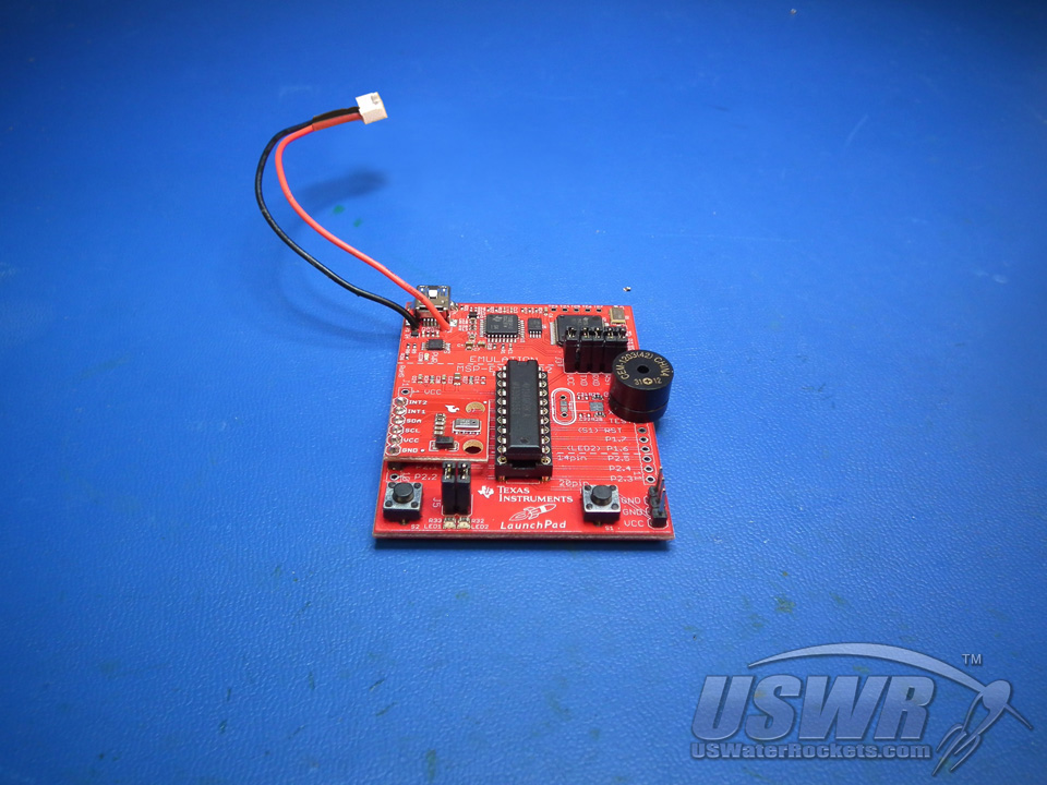
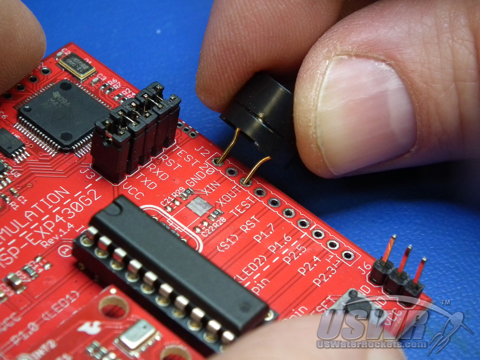
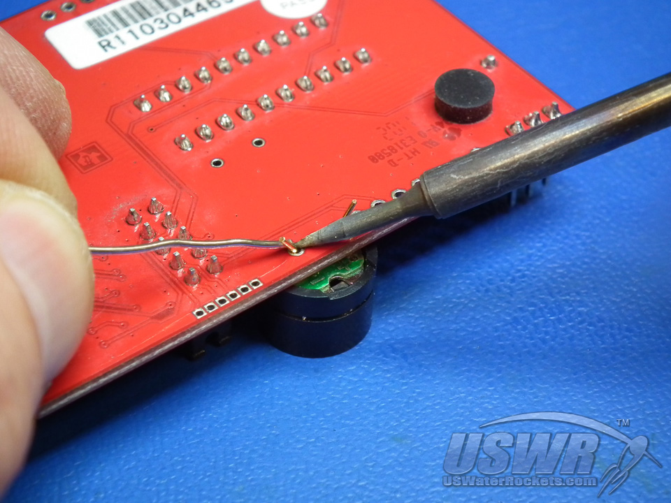
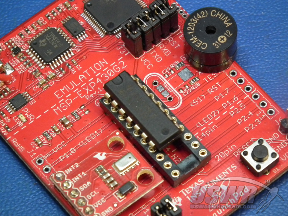
Step 6: Solder the audio enunciator to the MSP430 LaunchPad as shown:
If you want audio status sounds from your LaunchPad AlTImeter, you can install the optional audio transducer as illustrated. You will need to bend the pins closer together with a pair of pliers before installing because they are slightly wider than the holes provided. Note that one pin of the Audio Transducer is marked with a "+", and this must go into the hole marked "XOUT".

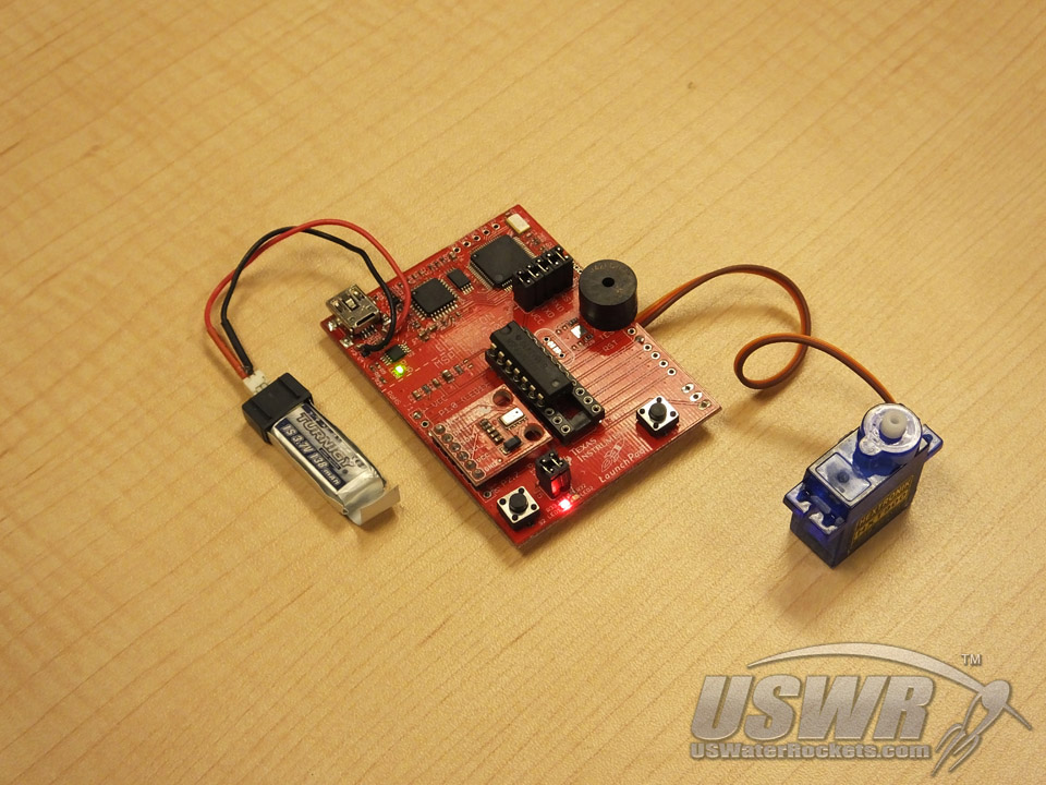
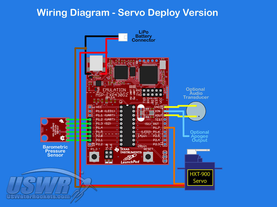
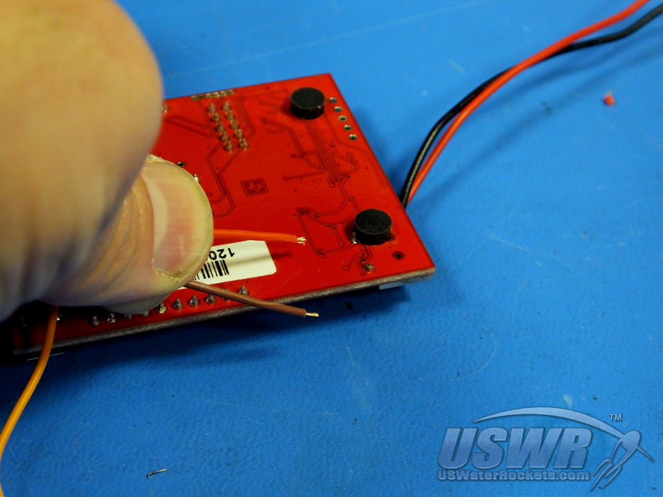
Step 7: Solder the servo to the MSP430 LaunchPad as shown (Servo Deploy Optional):
If you want to deploy a servo motor operated parachute with the LaunchPad AlTImeter, you can connect an optional servo. You can solder the servo directly to the LaunchPad AlTImeter, or use a JR type extension lead so that you can unplug the servo from the board in the future.Warning: Do not use the servo motor with the 9V battery power option. You will damage the servo!
To connect the servo, cut the female connector off the end of the servo leads, and solder the brown servo lead to the black battery lead. Solder the red servo lead to the red battery lead, and solder the orange servo lead to P1.7 hole in your MSP430 LaunchPad.


Programming:
The heart of the LaunchPad AlTImeter is an MSP430G Value Line microcontroller from Texas Instruments. This microcontroller contains flash memory which must be programmed with the LaunchPad AlTImeter software, to create the finished product. Follow the procedure below to load the firmware into the MSP430 LaunchPad:
Programming Step 1: Download LaunchPad AlTImeter firmware project:
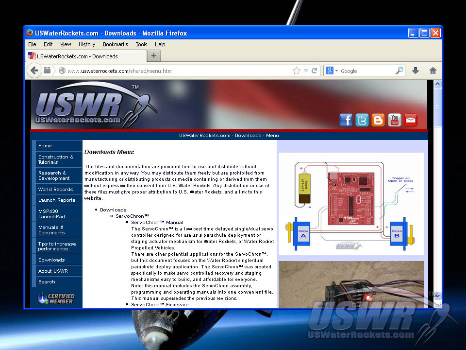
Click on the link provided below to download the firmware project file: LPAlt_V100.zip, and save the file on your computer.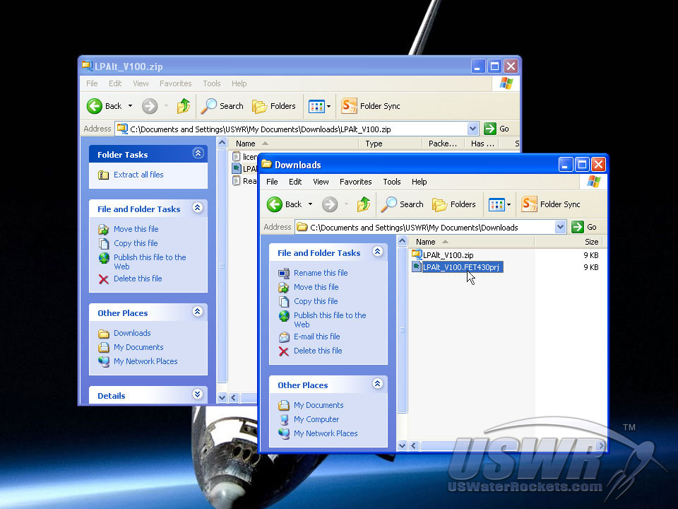
Programming Step 2: Extract the firmware file:
Open the file you just downloaded and drag the files into a convenient folder location on your computer.
Programming Step 3: Download the Programming Software Tool:
Go to the website http://www.elprotronic.com/download.html and download the free program called "FETPro430 Lite". When the download has completed, read the installation instructions and follow the procedures for installing the software and the USB drivers included. This is a third party utility and if you have difficulty with this step, you should contact Elprotronic for technical support with their utility.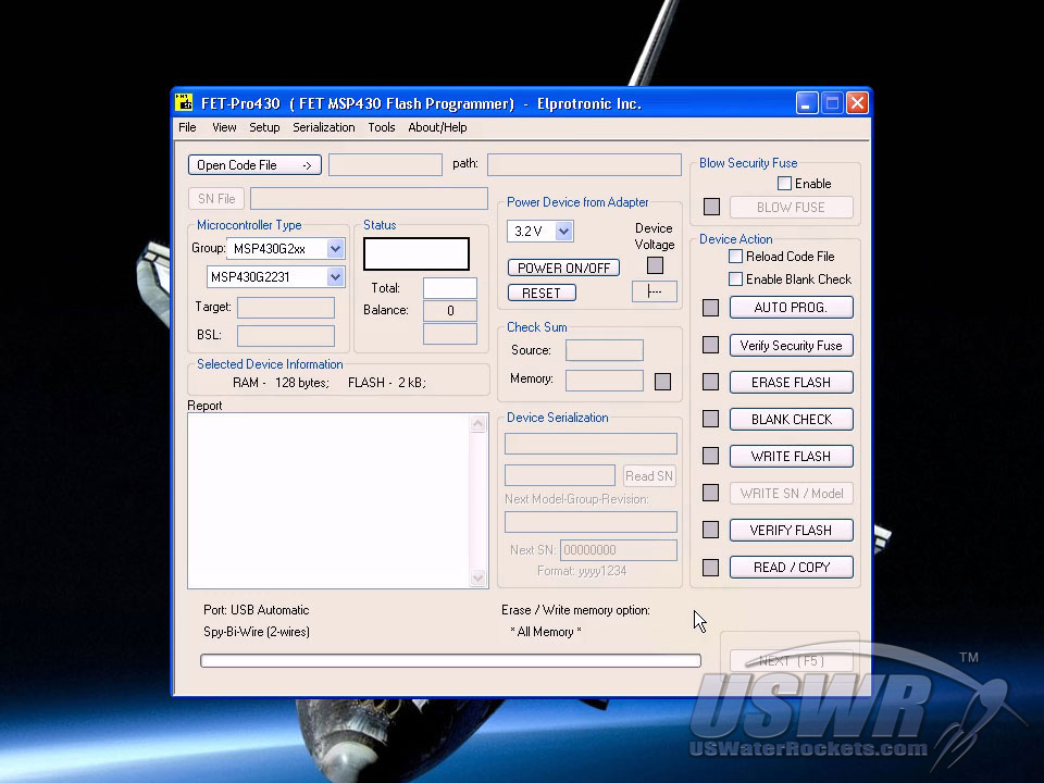
Programming Step 4: Launch the 3rd party programming utility:
Go to the "File" menu of the FET-Pro430 Lite application and click on "Open Project". You will then be presented with a file open dialog with which you will navigate to the directory where you saved the firmware project file. You select the firmware you wish to load and click "Open". The project file will then load into the programming application.
Programming Step 5: Program the Microcontroller on the MSP430 LaunchPad:
Disconnect any batteries from the LaunchPad, and connect a USB cable from your PC to the USB port on the LaunchPad.Warning: You must NEVER connect the battery and the USB cable at the same time. You can damage your PC or the LaunchPad, or cause the battery to explode.

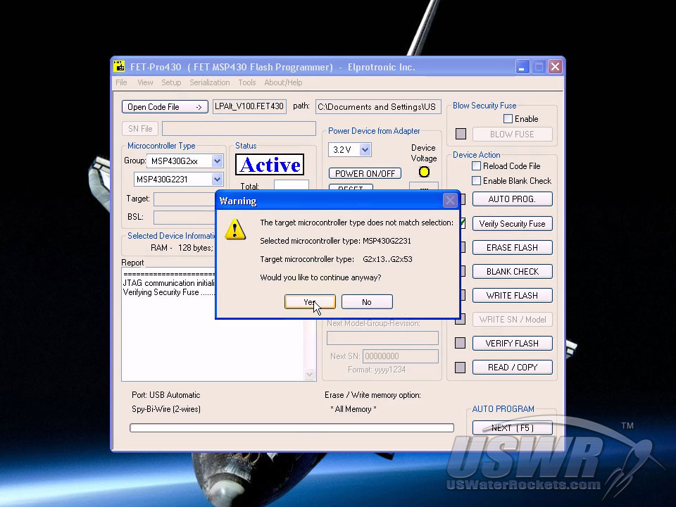
If your MSP430 LaunchPad is Version 1.5 or newer, it most likely has a microcontroller with a different part number installed on the board. The programming software will detect this different part and ask that you confirm the download is correct. Click on the confirmation 'Yes' button to proceed.
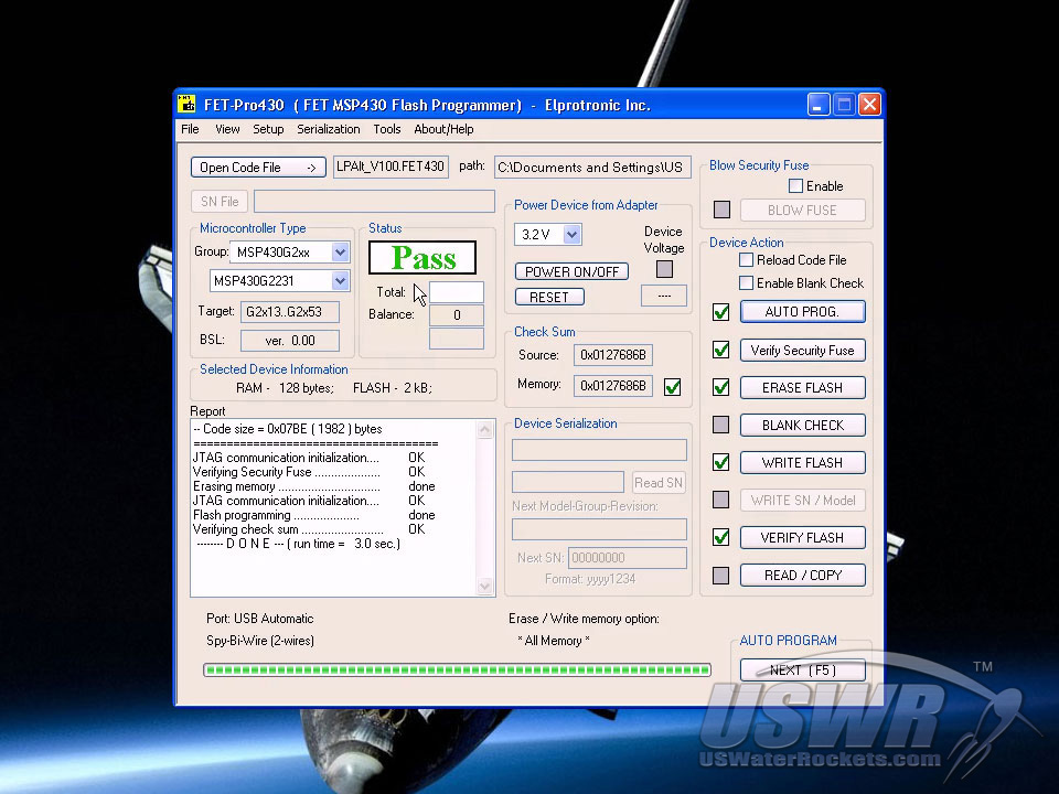
Programming Step 6: Finishing:
Congratulations! Your LaunchPad AlTImeter is ready for flight! Close the programming software and disconnect the USB cable from your computer. You are now ready to use your LaunchPad AlTImeter. You should now carefully read the installation guide section to learn the proper way to install the LaunchPad AlTImeter in your rocket. Improper installation can result in poor accuracy or even damage to the LaunchPad AlTImeter.If you want to add a Parachute Deploy system to your LaunchPad AlTImeter, please consult the Parachute Recovery section before continuing.
[Back to Table of Contents]
Installation Guide:
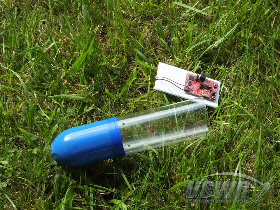
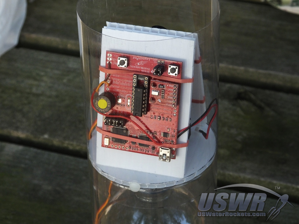
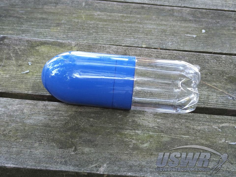
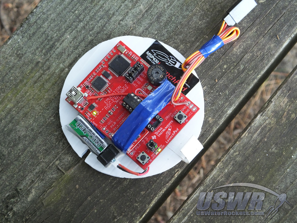
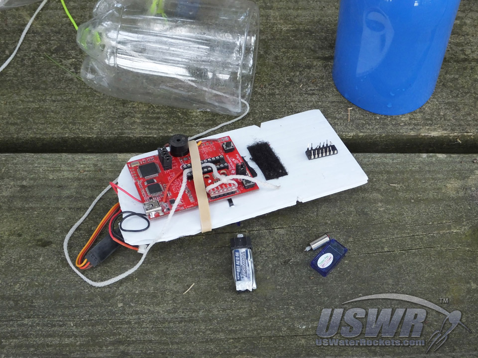
You will be installing the LaunchPad AlTImeter inside your rocket prior to launch so that it is carried with your rocket to measure the altitude. It can be oriented in any direction in any position that is convenient. More accurate readings will be recorded if the LaunchPad AlTImeter is secured to a bulkhead so that it does not shift around or get bumped during flight. We suggest affixing the LaunchPad AlTImeter to a piece of corriflute or cardboard with double sided tape.The LaunchPad AlTImeter must be installed in a compartment in your rocket that is not exposed to propellants, flames, smoke, liquids, or fumes from the rocket motor or ejection system or environment. This means you must install it in a compartment that is sealed from exposure to these substances. Water rockets must seal the electronics from contact with water!
The sealed compartment must have at least one hole in it to allow for the air pressure inside the compartment to change as the rocket changes altitude. These holes are called "Static Ports". One static port is required, but more ports spaced evenly about the circumference of the rocket is better because the additional ports reduce pressure variations caused by wind on one side of the rocket, unstable flight, and buffeting during descent. The exception to this rule is that two ports is not recommended. Use 3 or more if possible.
The ports must be round, and sanded smooth, with no burrs or ridges on the body tube.
The size of the static ports in your sealed compartment is important for getting the best possible results. A general rule of thumb is that for every liter of volume inside your compartment, you should have 4mm of port diameter. One hole of 4mm diameter or 4 holes 1mm in diameter will work well.
Avoid making holes less in diameter than the thickness of the compartment walls.
Avoid making holes smaller than these guidelines.
Avoid making holes over 2 times larger than indicated by these guidelines. It is important to note that the Barometric Pressure Sensor is so sensitive, that sunlight shining on it can cause the pressure reading to change, so you should not place the sensor in a location where it will be directly in sunlight. The light can cause faulty readings or even an unintended launch detect. We recommend making a shade from opaque vinyl tape to block sunlight from hitting the sensor but still allowing free air flow to it.

Parachute Deploy:
The LaunchPad AlTImeter has 2 available methods for deploying a parachute or triggering some other external event after apogee has been detected. The following instructions provide the proper connection methods and any extra modifications needed to utilize either one or both of the deploy methods. Consult the Wiring Diagrams in the Assembly Instructions Section of this manual for more example connections for deploy systems.Servo Motor Recovery:
This method uses a common servo motor to trigger a mechanical ejection system. Such a system is a prerequisite for Water Rockets, as pyrotechnic systems are forbidden in international Water Rocket Competitions like the WRA2 Competition Rules, and could even be illegal in your area.

| V+ | Power Supply for Servo (usually about 6VDC) |
| GND | Ground return for power supply |
| Control | Servo Control Signal |
This method of recovery often uses an electrically ignited pyrotechnic device to eject a parachute. The LaunchPad AlTImeter provides a 3.6V digital signal which can be used to activate an external driver circuit for such a deploy system. This output could also be used to trigger some other type of circuit, such as a camera shutter or telemetry indicator. To configure the active state for the External Trigger Deploy, see the Deploy Configuration section of this document. The connection terminal for the external Apogee Output is the XIN terminal. (See the Diagrams in the Assembly Instructions Section of this manual for more information).
If you wish to add a parachute deploy system to your rocket, we recommend you follow our tutorials for building a state of the art recovery system:
Parachute Tutorial
Radial Deploy Mechanism Tutorial
Axial Deploy Mechanism Tutorial
[Back to Table of Contents]
Configuration:
The picture below shows the front of the LaunchPad AlTImeter, and all of the controls you will use to configure the deploy settings.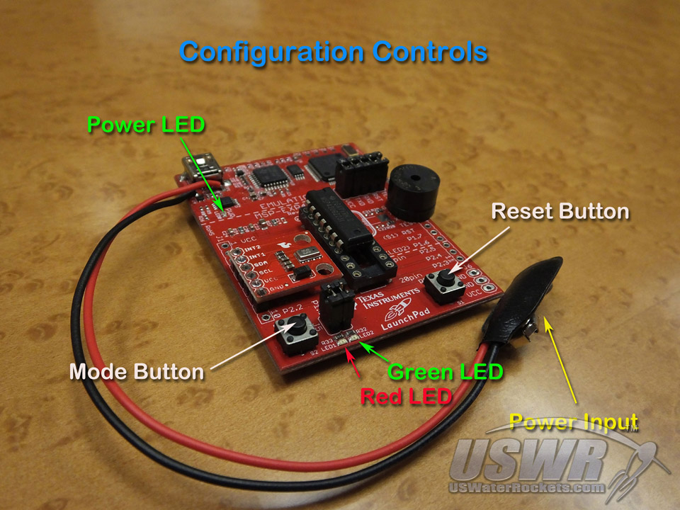
| Setting | Factory Default | Description |
| Deploy Delay | 0 Sec. | Time delay after apogee before deploy is triggered |
| Deploy State | True/Clockwise | Polarity of deploy output and direction of servo motor |
The following instructions allow these settings to be changed:
Setting Deploy State:
The parachute deploy output signals from the LaunchPad AlTImeter can be set to two different states, depending on what system you have connected.
If you are using an external igniter circuit the input signal required by that circuit will either deploy when the output from the LaunchPad AlTImeter goes high, or when it goes low. This will vary from one circuit design to another, so we have provided a way to define the deploy state of the digital deploy output.
If you are using a servo motor actuated deploy then the deployed position of the servo could be either clockwise or counter-clockwise. The direction depends on the mechanism you are using, so the position for the servo deploy is also programmable using this same method.
To program the Deploy State:
- Connect power to the LaunchPad AlTImeter with neither of the buttons pressed.
- Hold down the Mode button while pressing and releasing the Reset Button. The Red and Green LEDs will come on and stay on.
- Release the mode button and observe the Red LED. The Red LED will alternate between ON and OFF once every second. The state of the Red LED indicates the possible selections for the Deploy State.
- When the Red LED is indicating the desired Deploy State (see the table below), press the Mode button once more to save the desired Deploy State to permanent memory on the LaunchPad AlTImeter. The Deploy State will be preserved for every future launch until changed in this manner again, or new firmware is loaded.
| Deploy Type | Red LED Condition | Deploy State |
| Servo Motor | ON | Servo Fully Clockwise (Default) |
| OFF | Servo Fully Counter-Clockwise | |
| Deploy Output | ON | TRUE (3.6V) (Default) |
| OFF | FALSE (0v) |
You can program a delay from 0 to 30 seconds with this setting. You can use this to hold back the parachute deploy event for the desired number of seconds after apogee is detected. This is useful in a scenario where you want your rocket to descend for a number of seconds after reaching apogee and then deploy the parachute.
To change the Deploy Delay:
- Disconnect the power from your LaunchPad AlTImeter.
- Hold down the Mode button while connecting the power source. Both the Red and Green LEDs will come on and stay on.
- Release the Mode button. The Red LED will begin to flash once every second, counting up the delay time interval.
- Press and release the Mode button again when the Red LED has flashed the number of seconds you wish to set the Deploy Delay for. For example, press the Mode button after 5 flashes for a 5 second Deploy Delay. The Deploy Delay will be saved to permanent memory for every future launch until changed.
After either of these settings has been configured, the Red and Green LEDs will display the current version number of the loaded firmware. You can verify that you have the latest version loaded. See the Configuration section of this manual for more information.
[Back to Table of Contents]
Operating Instructions:
The LaunchPad AlTImeter is operated using the controls pictured in the image below: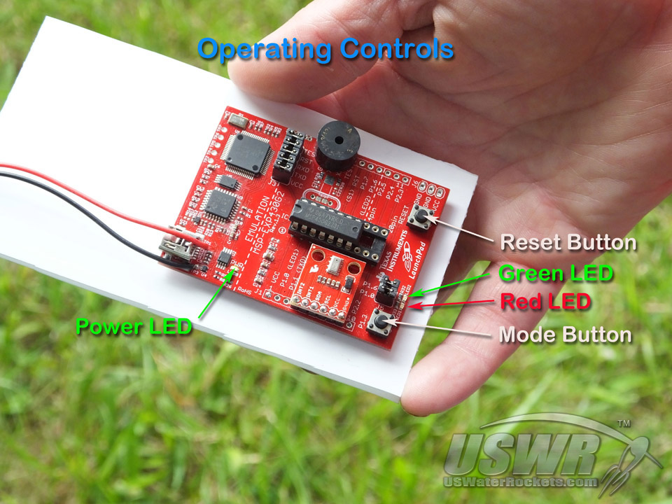
| Operating Mode | Description: |
| Apogee Reporting Mode | The altitude of the last recorded flight is reported |
| Deploy Configuration Mode | Make changes to the optional parachute deploy settings |
| Arming Mode | Operator initiated time delay before launch detect system is armed |
| Armed/Launch Detect Mode | System is armed and waiting for launch |
| Apogee Detect Mode | Launch is detected and system is detecting the apogee |
| Recovery Delay Mode | Apogee is Detected and Recovery Delay is in progress |
| Recovery Activation Mode | Recovery System is Activated |
| Error Reporting Mode | A configuration error was detected and the error code is reported |
| Hardware Failure Mode | A serious hardware problem was detected at power up |
| Show Firmware Version Mode | Operator initiated output of firmware version |
Apogee Reporting Mode:
When the LaunchPad AlTImeter has been powered up or reset with no control buttons pressed or has just completed a flight, it will be in Apogee Reporting Mode. In this mode the LaunchPad AlTImeter will report the altitude recorded on the last recorded launch. The recorded altitude is saved in non-volatile memory so that it will be retained even if the battery becomes depleted or disconnected.
The altitude report is displayed on the two status LEDs as well as using audible tones using a proprietary sequence of flashes/tones to report the height in feet of apogee. Use the following chart to decode the report sequence:
Note: The Red LED is associated with a low tone and the Green LED is associated with a high tone, so when the LED is indicated there will also be a tone generated if you have populated the optional Audio Transducer.
| LED Condition | Indication |
| Red LED ON for 2 seconds | Start of Report |
| Green LED flashes 0 to 9 times | Single Digit expressed as count of flashes |
| Both LEDs OFF for 2 seconds | Separator between digits |
For example, a flight of 935 feet would report the sequence:
- Red LED ON for 2 Seconds indicating the start of a report
- Nine flashes of the Green LED
- 2 second pause with both LEDs OFF, indicating the end of the first digit (9)
- Three flashes of the Green LED
- 2 second pause with both LEDs OFF, indicating the end of the second digit (3)
- Five flashes of the Green LED
- 2 second pause with both LEDs OFF, indicating the end of the third digit (5)
- The Red LED ON for 2 seconds indicating the start of the report again.
- Press briefly to start new report at the beginning. This is useful if you lose count and need to restart and are annoyed at waiting for the rest of the report. You can start over instantly by pressing MODE briefly.
- Press MODE and hold it for 1 second and release it to toggle the audio output until reset or armed. This option is useful if you want to avoid powering down the LaunchPad AlTImeter between flights, but find the beeping sound annoying. You can disable the audio reporting temporarily and turn it on later. Tip: if you can avoid repeatedly opening the rocket to access the battery, you reduce the risk of breaking wires or parts of the rocket from the wear.
- Press the MODE button and hold it for 5 seconds to initiate the ARMING sequence just prior to a launch. You must ARM the LaunchPad AlTImeter prior to each launch, otherwise it will not record a new altitude or deploy a parachute. See the section on Arming Mode for full details.
The Deploy Configuration Mode is used when you want to make changes to the settings used by the optional Parachute Deploy system that you can connect to the LaunchPad AlTImeter. The settings can be ignored if you are not using a parachute recovery controlled by the LaunchPad AlTImeter.
See the Deploy Configuration Mode for details how to use this mode to set up the recovery parameters.
Arming Mode:
Most commercially available altimeters automatically arm themselves after a short time interval once they have been powered up, only giving you a brief window of opportunity to close up your rocket and get it into position for launch. Often, the commercial altimeter will arm itself and begin waiting for launch detect before you are completely done, and handling of the rocket will cause a false launch detect and possibly activate the deploy system. To avoid this poor design, the LaunchPad AlTImeter uses the MODE button as an arming switch at any time when the LaunchPad AlTImeter is in Apogee Reporting Mode. You can bring the mode switch circuit to an external button for easy access, or press it with a skewer stick through one of the static pressure ports when you decide the rocket is ready for arming.
When you initiate the arming sequence, the LaunchPad AlTImeter flashes alternating Red/Green LEDs for 30 seconds to let you know it is preparing to arm. It also emits a Low/High siren sound for the first 5 seconds to audibly alert you that you have initiated the arming sequence.
During this 30 second time period, the LaunchPad AlTImeter will go through a series of self-calibrations to reduce the effects of ambient air pressure and weather conditions.
After 30 seconds, the LaunchPad AlTImeter will be armed and will emit a short beep once per second while waiting to detect the liftoff of the rocket.
Armed/Launch Detect Mode:
When the LaunchPad AlTImeter has armed itself, it begin to monitor the altitude changes it senses over time and calculates the velocity the rocket is moving upwards. A proprietary wind pressure cancelling algorithm senses a launch provided the rocket reaches an altitude of 30 feet or more. Once launch is detected, the LaunchPad AlTImeter enters Apogee Detect Mode.
Apogee Detect Mode:
When in flight after launch is detected, the LaunchPad AlTImeter begins to monitor the upward velocity of the rocket to detect when the rocket has ended upward movement. The altitude at this moment is recorded as the Apogee of the rocket and stored in nonvolatile memory in case of battery failure.
The velocity as the rocket is climbing is passed through a proprietary software filter that cancels out the pressure drop caused by the rocket passing through the speed of sound. This filter also cancels out the effects of wind and erratic flight, preventing incorrect apogee detection.
When Apogee is detected, the rocket then goes into Recovery Delay Mode.
Recovery Delay Mode:
If you have programmed a Recovery Delay time using the Deploy Configuration Options, this mode is a time delay between apogee and the trigger of the Parachute Recovery Output signals between 0 (default) and 30 (maximum) seconds. See the Deploy Configuration Section on how to change the delay.
When the Recovery Delay time has elapsed, the parachute Recovery Output Signals will activate the recovery system (either a Pyrotechnic Recovery, a Servo Motor Recovery, or Both). The Parachute Recovery Output signals will be active for 5 full seconds. After this time, the LaunchPad AlTImeter will revert to Apogee Reporting Mode.
Note: If you are not using either parachute recovery output of the LaunchPad AlTImeter, this mode is only a delay between Apogee and the time when the altitude is reported.
Recovery Activation Mode:
In this mode, the Parachute Recovery Output signals will be active for 5 full seconds. During this time the deploy system you have connected should deploy the parachute or some other recovery system. After this time, the LaunchPad AlTImeter will revert to Apogee Reporting Mode.
Error Reporting Mode:
After each flight, and after each power up or system reset, any configuration errors or problems are reported in this mode. This mode will read out errors in a similar way to the way that Apogee is reported in Apogee Reporting Mode, except the roles of the Red and Green LED are reversed. If the Red LED is flashing the count, then you will know that the count is an Error Number that is being reported.
The possible error codes are listed below:
| Error | Condition | Reason |
| 2 | Memory Error | A problem was detected writing to permanent memory |
| 3 | Sensor Error | The Pressure Sensor is reporting a failure |
Hardware Failure Mode
A serious hardware problem was detected. This can be caused by the CPU becoming physically damaged due to misuse or improper voltage, or it has not been programmed correctly. Improper connections of the wiring can also cause this error.
The error conditions are as follows:
| Error | Condition |
| Power LED ON, Red and Green LED OFF | Damaged MSP430 Microcontroller |
| Power LED ON, Red LED ON | Bad Programming of MSP430 or Pressure Sensor wiring error |
Show Firmware Version Mode
You can read out the currently installed firmware version by observing the LED indicators when this mode is activated. The firmware version number will blink a 3 digit value using the same blinking patterns used in Apogee Reporting Mode, except the 3 digits will report the firmware version. For example, the flashed code digits 1, 0, 0 would indicate firmware 1.00 version.
Two methods are provided to activate Show Firmware Version Mode:
- Loading new firmware activates this mode in place of Apogee Reporting Mode until a launch has been recorded.
- Manually configuring a deploy delay (any value, even 0), or manually setting a deploy state will replace Apogee Reporting Mode until the next launch is recorded. See the configuration setting section for more information.
[Back to Table of Contents]
Frequently Asked Questions:
In any product of this complexity, there are always going to be common questions that arise. This section groups together many of the basic questions people have about the LaunchPad AlTImeter. Please check here for the solution to any questions you may have before contacting U.S. Water Rockets. If you cannot find the answer to your issue here, then feel free to contact us with your question. You can post questions to us on The Water Rocket Forum, Facebook, or Twitter.
A. The reason the LaunchPad AlTImeter is so affordable is because you build it yourself from a small number of separate parts. We provide the plans and the software for free, and you easily build the hardware and save money. We're interested in helping people do it themselves, not manufacturing and distributing products.
Q. What's different about the LaunchPad AlTImeter that would make it worth building, as opposed to a commercially available Altimeter?
A. There are several reasons:
- The LaunchPad AlTImeter costs much less than other Altimeters because U.S. Water Rockets is giving away the firmware for free, and you build the hardware yourself.
- The LaunchPad AlTImeter is the latest release with the newest innovations. Technology is always advancing and you will always find superior performance in newer designs.
- The LaunchPad AlTImeter is the first Altimeter design specifically created to address the requirements of both Pyrotechnic and Water Rockets.
Q. What does the LaunchPad AlTImeter do differently than other Altimeters that makes it suitable for Water Rockets?
A. Once again there are several answers:
- It has the ability to drive a Servo Motor powered deploy system, which is the preferred method of parachute deploy for Water Rockets because the WRA2 competition rules forbid using black powder and similar types of pyrotechnic deploy systems. You can find great designs for servo deploy systems on our website: http;//www.uswaterrockets.com/construction_&_tutorials/menu.htm.
- Some water rockets are designed to accelerate very slowly and this can cause a regular altimeter to fail to detect the launch, resulting in no altitude reported, and no parachute deploy. Slow acceleration can also cause a regular altimeter to detect launch only after the rocket is well into flight. This results in a lower than actual altitude to be reported. The LaunchPad AlTImeter uses a proprietary launch detect system which can detect low acceleration launches but is also quite immune to false triggers due to wind gusts, if you follow the installation guidelines provided in this document.
- Combining the functions of a regular altimeter with the functions of a water rocket servo timer for less than half the cost of either one of those products, the LaunchPad AlTImeter helps to promote the sport of Water Rocketry.
Q. Where can I get the source code, so I can add my own features?
A. We have chosen not to publish the source code because this type of device could be easily modified from a hobby/educational instrument into something that could be used to hurt people or damage property. We are constantly adding new features to the basic design over time, so chances are anything you can think of to add to the software is probably already in the testing stage in our labs or in the field.
Q. Why can't I use the 9V battery option when I use the servo deploy feature?
A. Most small hobby servo motors are only rated for about 6V input power, so you would have two power sources on your rocket. To save room and space you can run the entire system from 6V.
Q. Does the LaunchPad AlTImeter work in supersonic rockets?
A. It was designed to work in this realm, but we have not yet flown it on a supersonic test flight to confirm it works properly. We have only conducted subsonic test flights at the time of release.
Troubleshooting:
This section will help you resolve the most common problems that people encounter with the LaunchPad AlTImeter.From time to time you may encounter an issue that you do not understand. Use this troubleshooting guide to help resolve problems.
| Issue | Resolution |
| The altitude started reporting while I was setting up to launch. | • A pressure variation that resembled a launch pressure drop has triggered the launch detect. |
| The altitude started reporting while I was pressurizing my water rocket. | • Be careful not to flex rocket while handling it, causing pressure changes inside. |
| The altitude started reporting while I was waiting to launch. | • Make sure pressure leaks from within pressurized components of your rocket are not affecting the readings. |
| • Make sure sunlight is not hitting the pressure sensor, leading to bad readings. | |
| • Windy conditions in combination with poor air inlet portals can cause false triggers. Refer to the installation instructions for proper inlet design recommendations. | |
| The height reported is impossibly high. | • A pressure fluctuation has caused sufficient false altitude readings to register as a valid data point. This is usually caused by a very unstable rocket flight, or a crash event. |
| My rocket did not report a flight. | • There can be several reasons for this: |
| • You did not arm the system before launching. | |
| • The rocket did not achieve sufficient speed or altitude to trigger a launch. | |
| • The pressure inlet ports are too small or have become blocked. | |
| • The battery became disconnected before the launch event. | |
| • A crash event disrupted the launch detection system. |
For technical support, please use the LaunchPad AlTImeter technical support forum.
[Back to Table of Contents]
Specifications:
| Measurement: | |
| Resolution: | < 1 foot (30 cm) |
| Minimum Apogee: | ~32 feet AGL (10 meters) |
| Maximum Apogee: | ~32,500, AGL |
| Minimum Altitude: | -1,800 feet ASL |
| Maximum Altitude: | 37,200 feet ASL |
| Calibrated Accuracy: | +/- 1% max |
| Analog/Digital Converter: | 24-bit |
| Sampling Rate: | >100hz |
| Slow Launch Detect: | Yes |
| Wind Gust Filter: | Yes |
| Nonvolatile Memory: | Last Apogee and Deploy Settings |
| Deploy: | |
| Digital Output: | 0VDD and 3.6VDC at 5mA Max |
| Servo Output: | 0.5ms to 2.5ms at 50Hz, 3.6VDC p-p |
| Deploy Event Duration: | ~5 seconds |
| Operator Interface: | |
| LED's: | Power (1 Green), Status (1 Green, 1 Red) |
| Switches: | Reset (S1) and Mode (S2) |
| Audio Enunciator: | 85dB |
| Power Requirements: | |
| Current Required: | 25mA average (Add 10mA if Audio Enunciator is used) |
| Battery Input: |
3.7VDC to 10VDC (Non-Servo Configuration) 3.7VDC to 6VDC (Using Servo Parachute Deploy Configuration) |
| Battery Life: | 40+ Hours on typical 9V transistor battery (non servo version) |
| Environmental Requirements: | |
| Operating Temperature: | -20°C to +60°C |
| Storage Temperature: | -40°C to 90°C |
| Battery Life: | 40+ Hours on typical 9V transistor battery (non servo version) |
[Back to Table of Contents]
 LaunchPad AlTImeter by
U.S. Water Rockets is licensed under a Creative Commons Attribution-NonCommercial 3.0 Unported License.
LaunchPad AlTImeter by
U.S. Water Rockets is licensed under a Creative Commons Attribution-NonCommercial 3.0 Unported License.