How to construct a Launch Detect Acceleration Switch
Introduction:
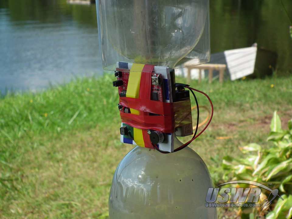
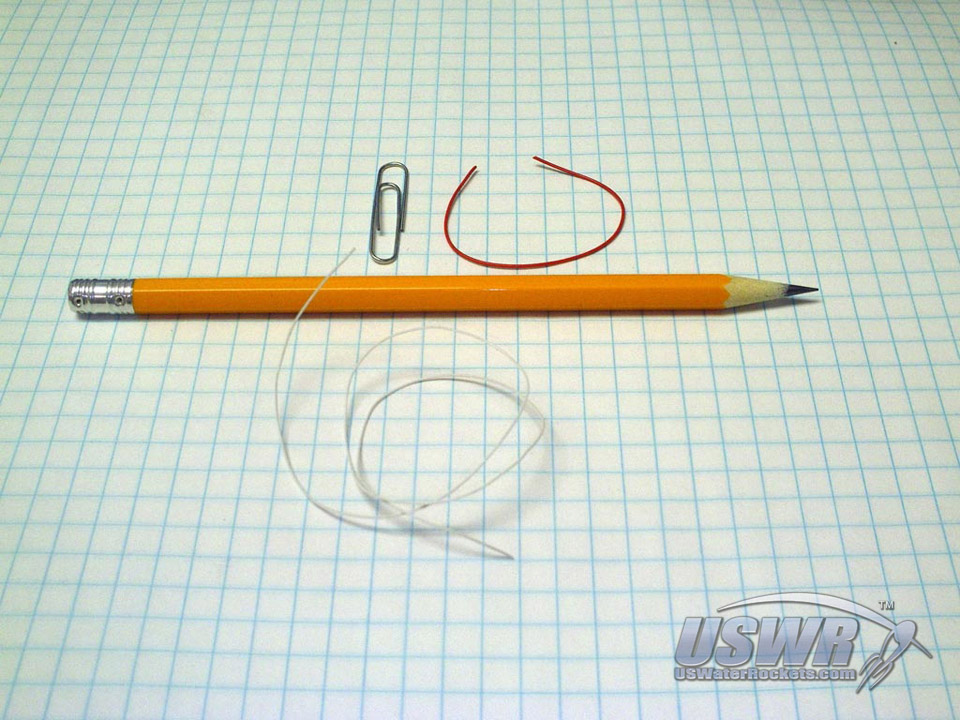
This tutorial will show you have to construct a very reliable and lightweight acceleration switch which you can use to activate electronic systems on your rocket such as a ServoChron™ 2 Dual Servo Actuated Parachute Recovery System. You can see a video explaining the ServoChron™ 2 on our YouTube Channel.- 8" of #28 AWG solid copper wire (plated wire if possible)
- 2" of #26 AWG solid copper wire (plated wire if possible)
- 1 PET plastic soft-drink bottle
- 1 Paper Clip
- Solder
- Wire Cutters
- Soldering Iron
- Sharp Pencil
Materials Required:(See photo gallery for alternate materials)
Tools Required:
Step 1: Create the circular switch contact eyelet:
Strip any Insulation off the #26 solid copper wire, then wrap the #26 wire around the tip of the pencil and twist the ends together. Use the thickness of the pencil lead as a guide to creating a 0.1" loop inside diameter. You can use a small nail or other thin rod in place of the pencil lead if you have something similar to substitute for the pencil.Feel free to adjust the size to suit your personal needs. A larger eyelet will reduce the sensitivity of the switch but this may be a trait you desire. A less sensitive switch will be less likely to accidentally trigger while you are handling the rocket.
Slide the loop of wire off the pencil tip when it is completed and add a little solder to the pigtail. You should now have a wire eyelet with an inside diameter of approximately 0.1" and a short pigtail coming off the edge. The first component is now complete.
Gallery
Step 2: Turn the soft copper wire into hard copper wire:
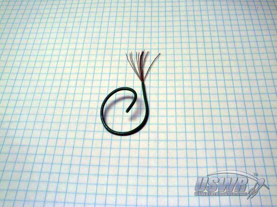
Strip any insulation off the #28 wire, and wind the #28 wire around the pencil. Neatness doesn't matter. Just wind it around and then slide the wire coil off the pencil, then run it through your fingers to straighten it back out. Repeatedly coil and straighten out the wire several more times. A total of 10-15 times should be sufficient. What we are trying to accomplish by doing this is what is known as "work hardening" the copper. Copper becomes harder and stiffer as it is shaped and "worked", and loses stiffness when it is annealed with heat. Our goal is to "work" the copper to harden it into "spring" copper. We work harden the wire this way to eliminate the softness from the copper. ...Gallery
Step 3: Coil the wire into a spiral:
Take the paperclip and bend away the one end leaving the wire protruding out, making sure the protruding wire is straight and round and free from burrs or defects. Next, coil the #28 copper wire around the protruding lead on the paper clip. Leave an inch or so of the end dangling. After coiling the wire, push the wire together to pack the coils side by side so they touch and form a perfect spiral. Keep going until you have about 1/2" of packed coil and then clip off the excess and pack the end down neatly.Gallery
Step 4: Turn the spiral into a spring:
With your fingers, gently pull the coils lengthwise to spread them evenly out with a small gap between each coil. The overall length of the coil will only grow 0.1" to 0.2" in this process. Now you can remove the coil from the paper clip. You should now have a neatly wound copper spring with a wire leg on one end.Gallery
Step 5: Determine a mounting location for the parts:
You will need to have a location on your electronics circuit board prepared for the g-switch. This design was created such that you only need to drop down a through-hole resistor package in the board location for the switch. You do not need to design a custom footprint for the switch, which is a nice feature. You can also simply mount the parts onto a small piece of plastic or wood and connect wires instead of using a printed circuit board. Use the following steps as a general guide for mounting.Gallery
Step 6: Test the Spring:
If you take the copper spring and hold it in a pair of pliers, you will notice that it is very sensitive to shock forces. It will oscillate quite a bit with a very minor perturbation. This should give away the secret how this g-switch operates.Step 7: Mounting the contact eyelet:
Carefully solder the eyelet into one end of the resistor pads on the circuit board. Make sure it is slightly raised from the board and perpendicular to the resistor component package and vertical.Gallery
Step 8: Mounting the spring:
Solder the leg of the spring into the opposite resistor package pad on the circuit board. The opposite and of the spring is inserted through the eyelet before soldering. Take care not to heat the spring too long or it will anneal and soften. You may wish to put the paper clip back inside the spring for the soldering step to draw away the heat from the copper wire. When finished with this step you may need to bend the leg of the spring around with the pencil point until the loose end of the spring is perfectly centered inside the eyelet. Adjust the spring until it is centered inside the eyelet and not touching the sides or any other metal parts on the circuit.Gallery
Step 9: Make a cover for the delicate switch:
Cut a piece of the plastic soda bottle about 3/4" long and 1/2" wide. Curl it around the pencil and make it into a 3/4" long "U" shape. Continue to bend and form and work the plastic until it holds the desired shape. Next, Invert the plastic U and glue it in place over the top of the spring/eyelet on the circuit board. The plastic acts as a shield to prevent the g-switch from being bumped accidentally or knocked out of calibration.Gallery
Finish:
The g-switch is now complete. Any shock perpendicular to the spring will cause it to oscillate and touch the eyelet, completing the circuit between the two pieces. An acceleration perpendicular to the spring will bend it to the side and also complete the circuit.To use this switch in a circuit effectively you will need to latch the contact closure because the switch will open back up immediately after making contact. If you have a microcontroller circuit reading the g-switch, it is a good idea to use an interrupt pin triggering a software action upon the transition of the signal when the contact closes. The ServoChron™ hardware was specifically designed to work in just this manner. If you do not use a microcontroller then you will need to add a flip-flop or some other type of one-shot circuit to latch the signal when the contact closes.
The design can be scaled up or down in size if you prefer, and sensitivity can be adjusted by varying the length of the spring. A longer spring will be more sensitive because it has more mass and leverage. Sensitivity can also be changed by changing the eyelet diameter. A smaller eyelet will be more sensitive because the spring will not need to deflect as much to reach the contact point in the eyelet. Be careful in making the switch too sensitive as it has been known to respond to minute vibrations in the ground such as those caused by nearby cars or even thunder claps.
Launch Detect Acceleration Switch Video Tutorial:
 Water Rocket Launch Detect Switch Construction by
U.S. Water Rockets is licensed under a Creative Commons Attribution-NonCommercial 3.0 Unported License.


