


How to build a Cable Tie Style Water Rocket Launcher.
Introduction:
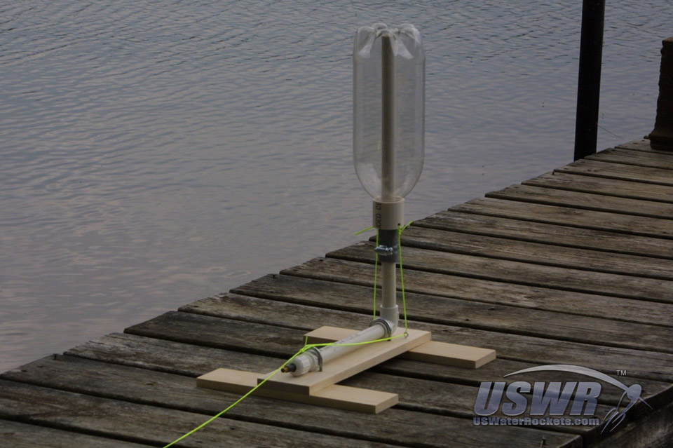
What good is building a water rocket if you have no way to launch it? This tutorial will explain in detail how to create a very easy to build, yet extremely robust and reliable water rocket launcher. The launcher has been designed so that no special tools or skills are needed to assemble it, and it uses commonly available parts which you can find at a hardware store or lying around the house.The launcher we will be constructing is a variation of the Clark Cable Tie launcher, as this is the most reliable launcher that is easy to make. This launcher style is also very robust and reliable and will serve for many launches without breaking or needing any adjusting or maintenance at all. This type of launcher will work with virtually any type of water rocket from simple empty bottles to high pressure reinforced FTC rockets.
Tools and Materials Required:
-
Materials Required:
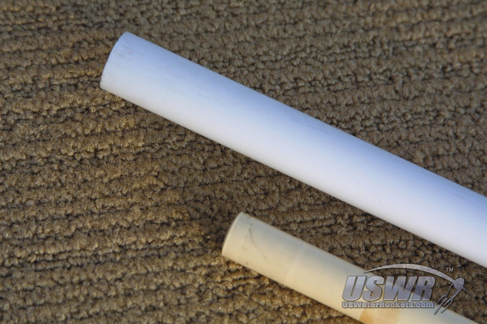
- 3 feet of 1/2" PVC pipe
- 3 inches of 3/8" PVC pipe (If you cannot find 3/8" PVC pipe for your launch tube, you can substitute in a piece cut from a chap-stik lip balm tube, or a piece of 1/2" copper pipe)
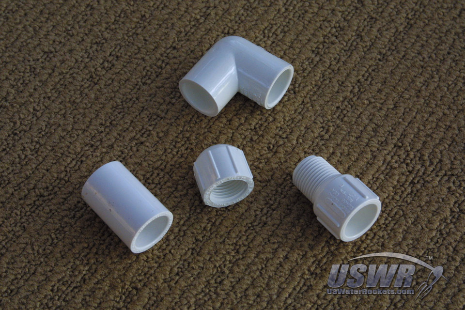
- 1/2" 90 degree PVC elbow joint
- 1/2" female to female PVC coupler
- 1/2" Female PVC to male threaded adapter
- 1/2" threaded PVC end cap
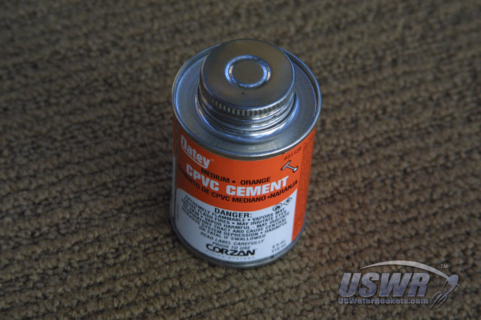
- PVC/CPVC cement
- #22 O-ring (0.1" thick and has a 1/2" inside diameter)
- Tire valve
- Garden Hose Washer
- 1.5" diameter hose clamp
- 6" Cable Ties or Zip Ties
- PVC Coupler or Pipe for Collar (Size to be determined by your bottle size)
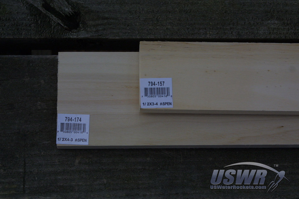
- 3 feet (approximate) of wood 1/2" thick by 4" wide (or larger)
- 2 1.5" radius U-Bolts
- String or small rope (50+ feet long)
- Small screw eyes
-
Tools Required:
- Scissors
- Screwdriver
- Electric Drill
- Safety Glasses
- Small carpenter's square
- Wood Saw
- Sharp Knife
Step 1: Cutting the PVC pipe components:
The launcher will require several pieces of 1/2" PVC pipe to make up the base. The dimensions are arbitrary in this design so they do not have to be exact. You may change the dimensions to suit your tastes or personal preferences. The pieces we will need areas follows:About 8 inches for the base tube. About 4 inches for the riser tube. About 12 inches for the launch tube (this will vary depending on your rocket length).
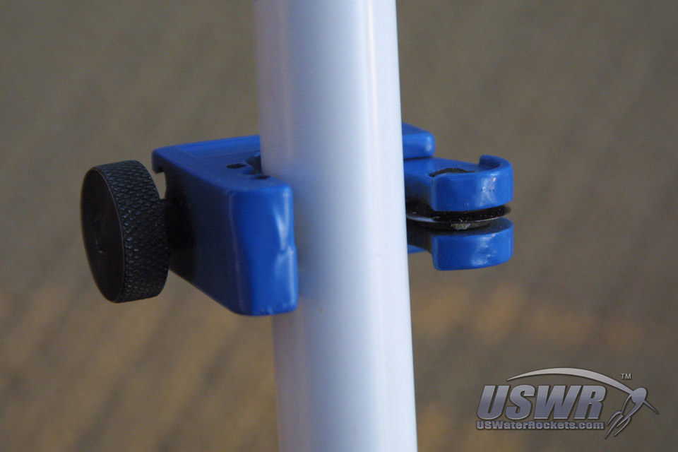
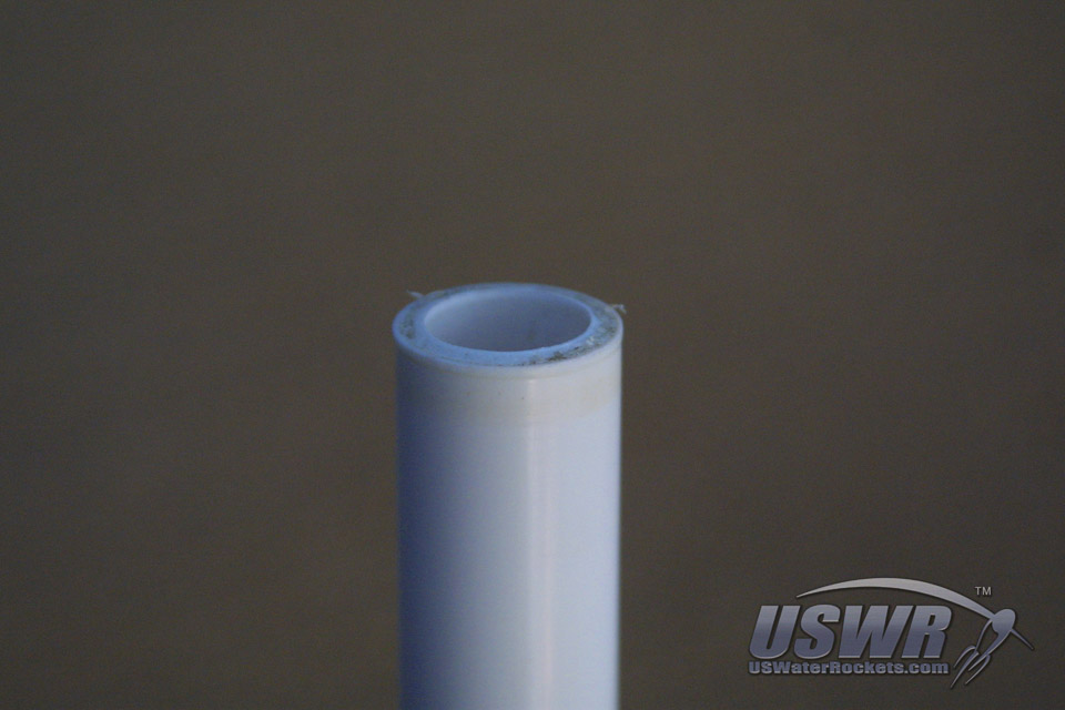
We mark our 1/2" PVC pipe and cut it. There are several methods that can be employed to cut our pipe. You can use a simple and inexpensive tubing cutter which will cut a nice straight cut at a perfect right angle across the pipe. This style of cutter has a circular blade which is drawn into the pipe by a screw clamp mechanism. You gradually close the clamp down on the pipe as you rotate the blade around the circumference by hand. After a short time the blade will work completely through the pipe. A drawback of this type of cutter is that it leaves a small ridge of excess material around the outside of the cut edge. This can make the pipe difficult to insert into fittings. Also, due to the fact that the cutting blade is wedge shaped, the cut in the pipe will come out angled slightly toward the inside edge of the pipe wall. This isn't a problem usually, but on exposed pipe ends it can be a cosmetic flaw you may want to avoid.
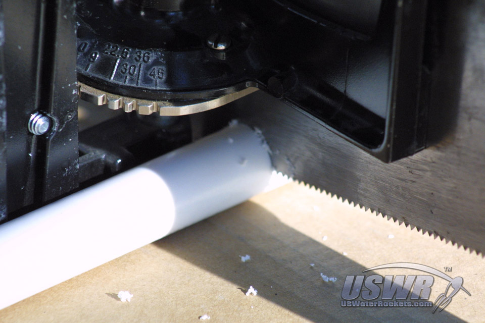
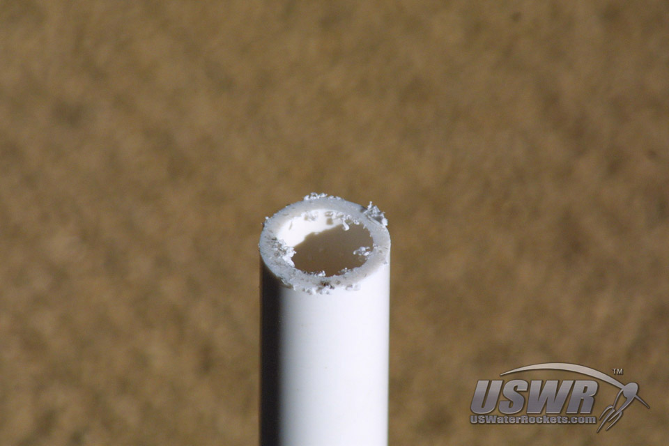
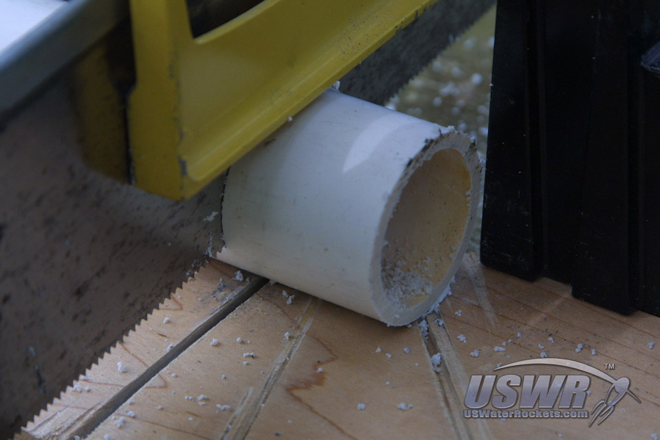
Alternatively, pipe can be cut with a saw. Cutting carefully can result in a very nice cut, but it is quite difficult to get a perfectly perpendicular cut on a round object. That is why we recommend using a miter saw or a miter box for a hand saw. This type of tool will hold the saw perfectly perpendicular to the pipe and produce a perfect cut every time. Shavings and shards will likely be left on the edges of the cut. The blade may also leave grooves in the edge of the cut and this may be unsightly. We want to at least remove the shards and clean up the end of the pipe so it will be easy to assemble and glue.
Gallery
Step 2: Sand the PVC pipes:
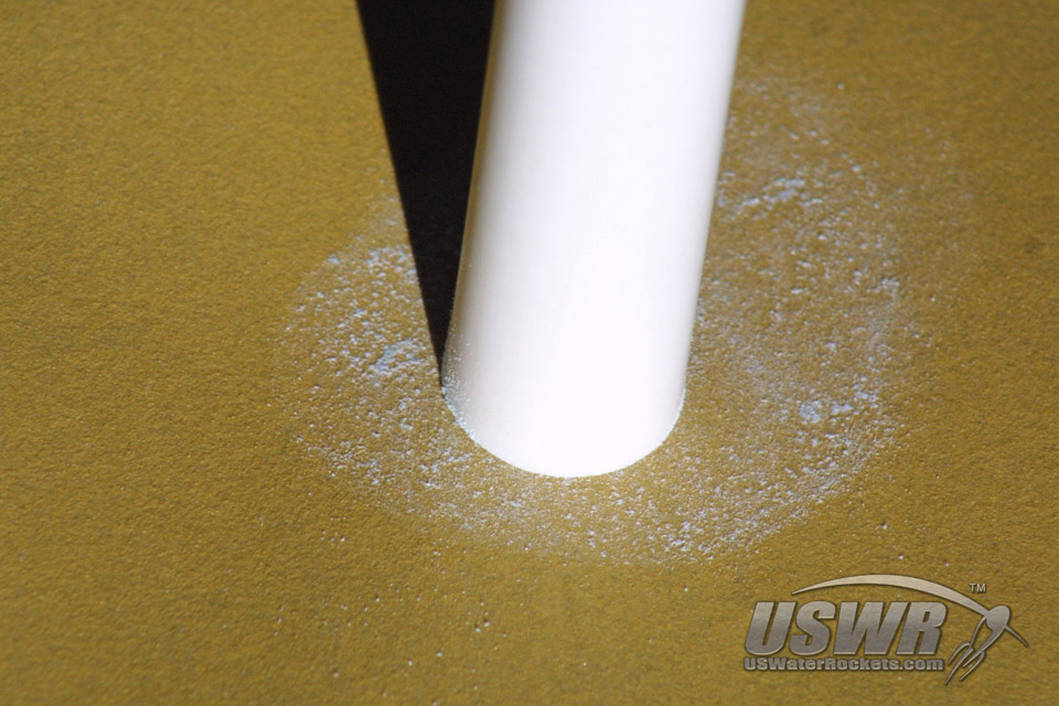
Some simple sandpaper can work miracles on our cut pipe. If you use the pipe cutter to cut your pipe, you can get rid of the ridge and even square up the cut. If you use a saw to make your cuts, you can clean up the shavings and smooth out the end for a perfect looking pipe end....
Gallery

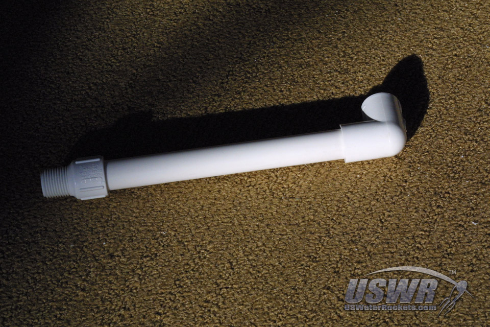
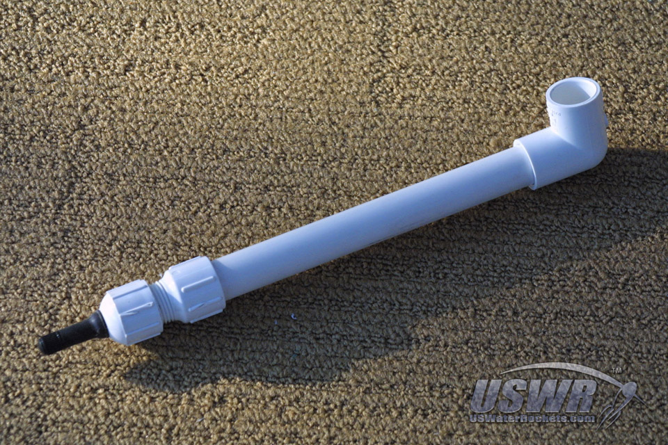
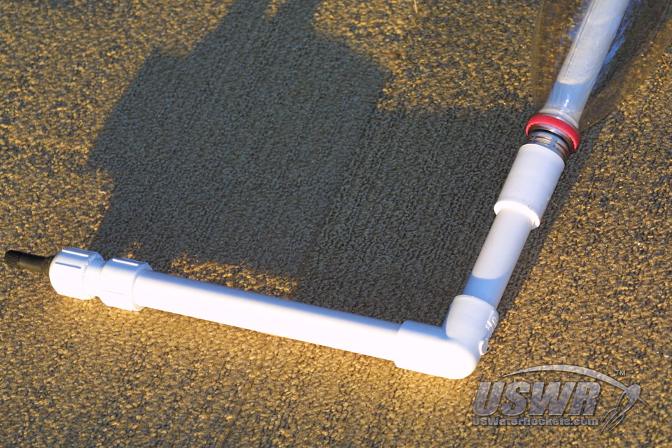
Step 3: Test fitting the components:
We will now temporarily assemble the base tube of our launcher now. Do not glue anything yet, we are just test fitting the launcher parts. First put the Elbow on one end of our cut pipe.Next, we will put the threaded coupler on the other side. Remember, do not glue anything yet!!! You can already get a good idea how our launcher is going to look when finished.
Gallery
Step 4: Drilling a hole for the Schrader (tire) valve:
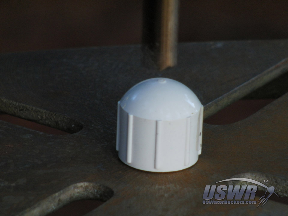
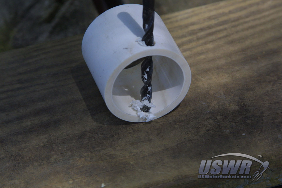
This step illustrates a simple way to connect a Schrader valve stem to the water rocket launcher. This method is very simple and provides a built-in safety mechanism which is always a good thing. For those of you who prefer the "Presta" type valve stems, we will suggest some alternative methods you may use to connect those types of valves to the launcher as well, so don't despairThe first thing we will need is to take out the threaded PVC Pipe end cap and locate the center of the end of the cap. We picked out these fancy domed style caps because they have a bit of mold flashing at the exact middle of the top of the dome, which located the center with exact precision.
If you don't have a handy mark on your cap, use a pencil or pen to mark the center as best as you can. If you can spin the cap or roll it on a table top you would be able to see with the naked eye if the center mark is correct because the mark will not wobble when you get it in the right spot. Once you have the center position marked, you can drill a small pilot hole if you want to. Some people have better luck without a pilot hole in the cap and can keep the drill centered better without one. Whichever you prefer we will leave up to you.
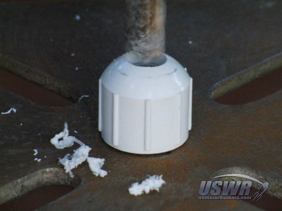
The magic of the build happens when you choose the drill bit to make your hole in the end cap. Take your Schrader valve and notice that it has a small groove molded into the bottom of the stem. This normally fits through the hole in the wheel in the tire and is what holds it in place. That is the same thing we will do here. You will need to find a drill bit which is a little smaller than the groove to make your hole in the end cap. The size of the drill is not critical just make sure it's a little narrower than the groove.
With the drill bit selected, we can now begin to drill the hole. We have a drill press that makes a nice hole but you can use a hand drill as well. The nice part about the drill press is that it has a hole in the platform that we use to screw the pieces down from the bottom side and hold them in place.
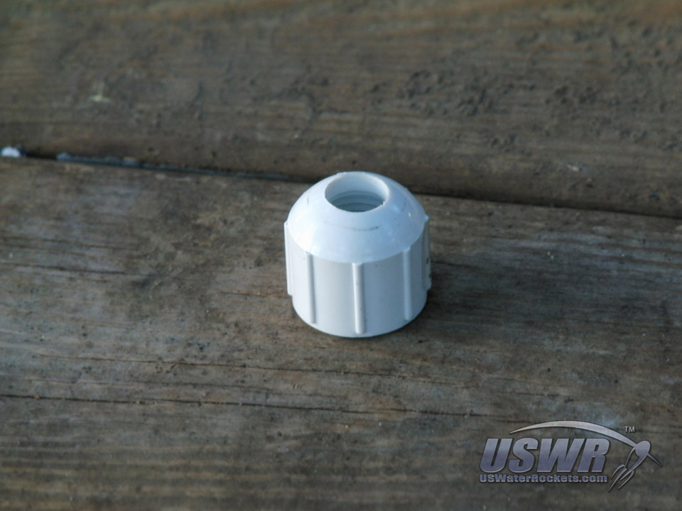
When finished with the drill, you should end up with a threaded cap with a nice clean hole in the end. If the edges of the hole are not clean and smooth, you can correct this with a rolled up piece of sandpaper. Just insert the sandpaper into the hole and sand the edges nice and smooth. Don't sand the edges too much or you will enlarge the hole too far.
Gallery
Step 5: Installing the Schrader Valve:
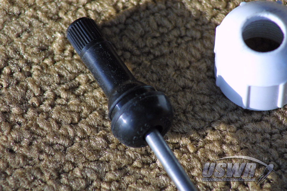
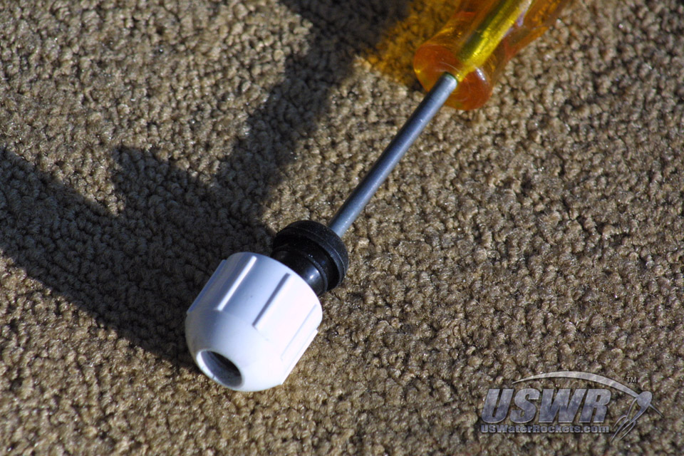
The next part of the launcher build is to install the Schrader valve. The way this is accomplished is the same way that the valves are installed in a wheel of a car. Many people are tempted to stick the valve through the hole and pull it through from the other side with a pair of pliers but this is not the way it is done. It could ruin the valve if you pull it through this way.The proper method is to use a tool to insert the valve from the opposite side. If you do not have the special tool, you can use an awl or a Phillips screwdriver to accomplish the same thing. Insert the tool into the bottom of the valve and insert the valve in the hole.
A hard push of the tool will elongate the rubber valve stem and it will easily push the step through the hole into the groove and it will lock in place forming a perfect seal.
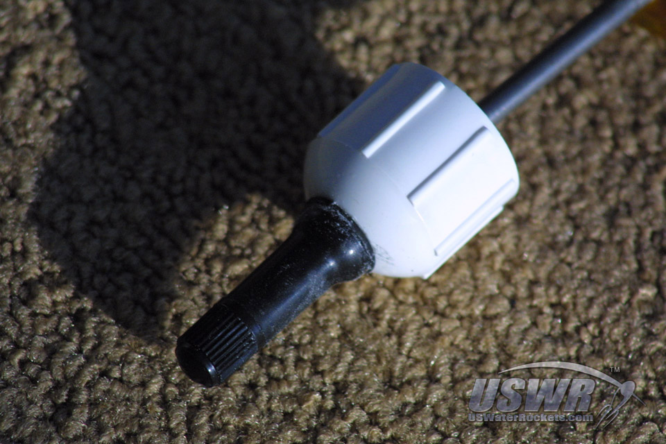
The completed valve assembly not only provides a connection for the air pump, but it will also act as a safety device. The Schrader valve is not glued in place and therefore it can provide some degree of safety because the valves will tend to pop through the hole if the pressure gets too high. We have tested this and it works with the launcher we made. You should test this on your own design because not all valves and caps will be the same.
Note:
If you use Presta valves, you can actually mount them by drilling a hole through the cap and putting a nut on either side of the cap to hold the valve in place, along with some glue to seal the hole. It's not quite as easy to make, but it will work.
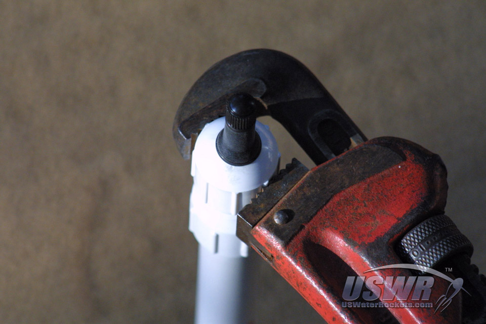
The complete cap assembly can bow be screwed down onto the end of the launcher at the threaded coupler position. The threaded coupler just needs to screw into place. Do not worry about screwing it down too much because it could begin to force the valve out of the hole if you put too much pressure on it.
Gallery

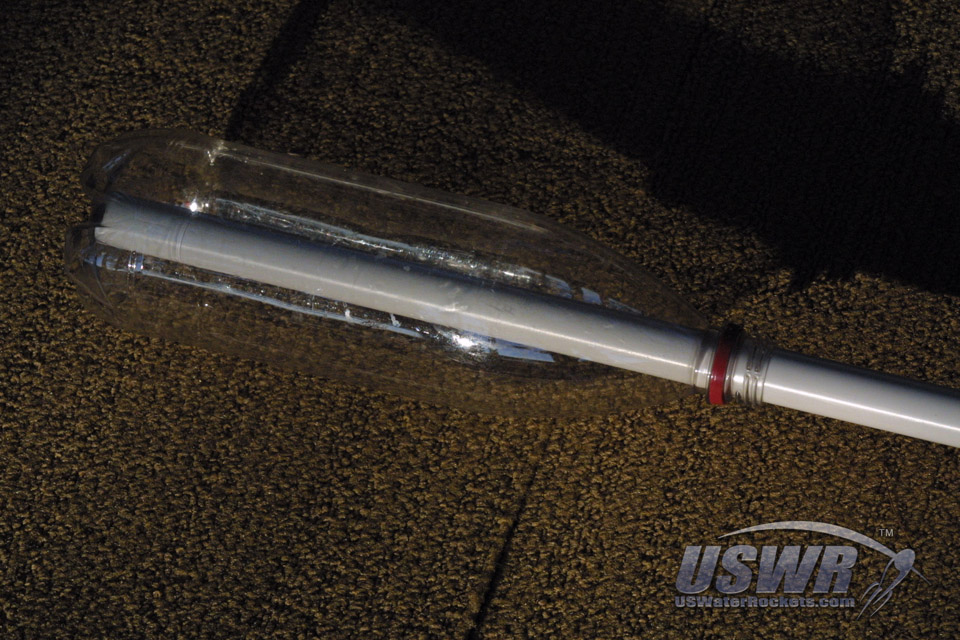
Step 6: Preparing to glue the splice:
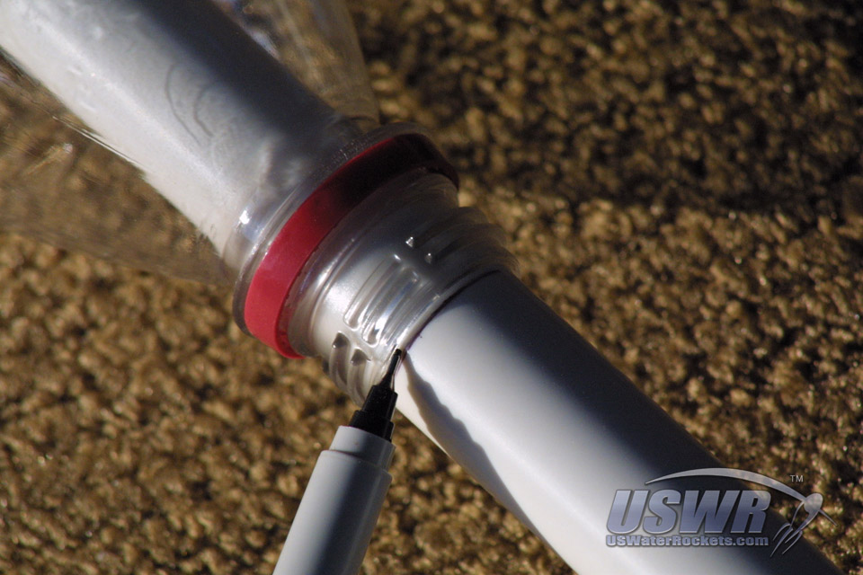
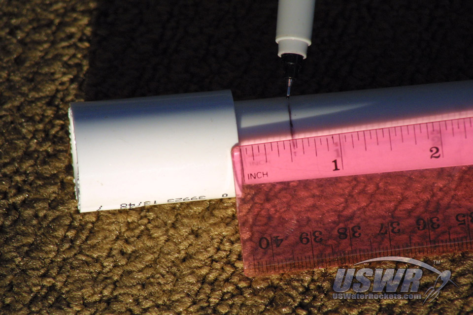
Insert a piece of 1/2" PVC pipe (the basic form for your launch tube) into your water rocket as far as you wish it to extend inside. The pipe should not be so long as to touch to top of the rocket when the tube is completed, otherwise it could block the air flowing into the rocket. Keep in mind that the amount we measure here will be reduced by the amount that is inserted into the female-female PVC coupler so if you just push the tube in all the way and mark it you will have a part that is guaranteed to fit with a small gap at the top for the air to get in.Mark the pipe where you want to cut it and saw it off as described earlier in this tutorial. To keep it simple, we're not going to measure any of this exactly, we will just put a mark on the launch tube using the neck of the bottle as a guide.
Once you have cut the PVC launch tube and cleaned up the end, you will now insert the pipe into the PVC 1/2" Female-Female Coupler. This coupler is used to join 2 pieces of 1/2" PVC Pipe together. In our case, we will be using it to form a base for the rocket nozzle and a ledge for the cable ties to affix to. This will prevent the ties from slipping off under pressure. We are using cable ties for our launcher as inspired by the fine work of Ian Clarke who invented this idea many years ago before disappearing from the water rocket scene.
Gallery
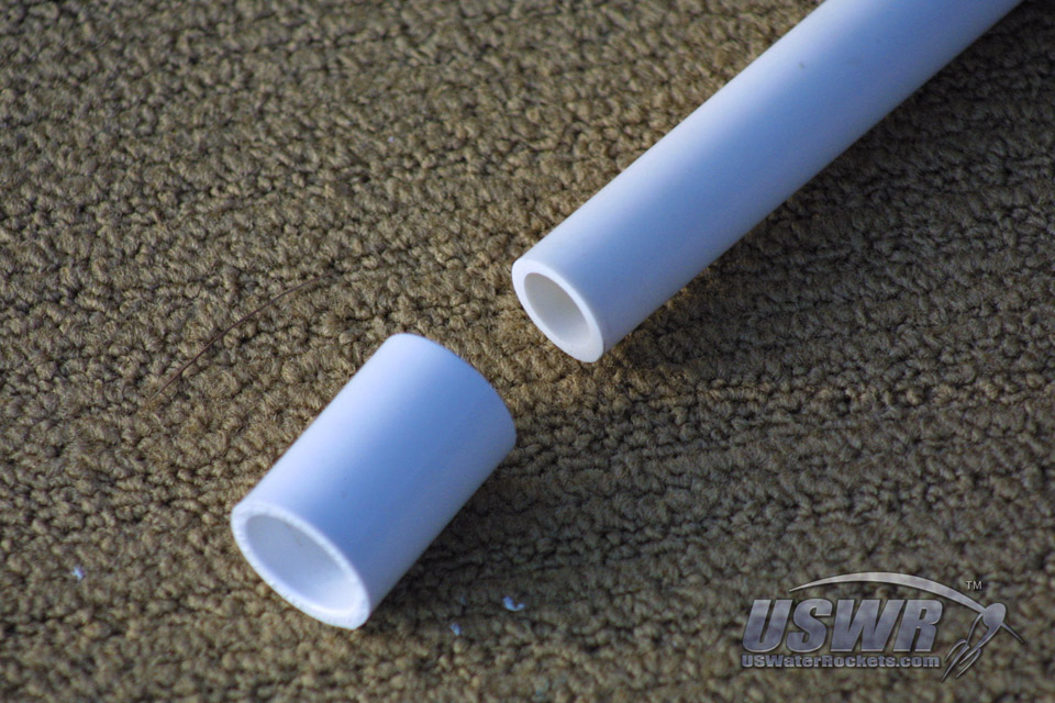
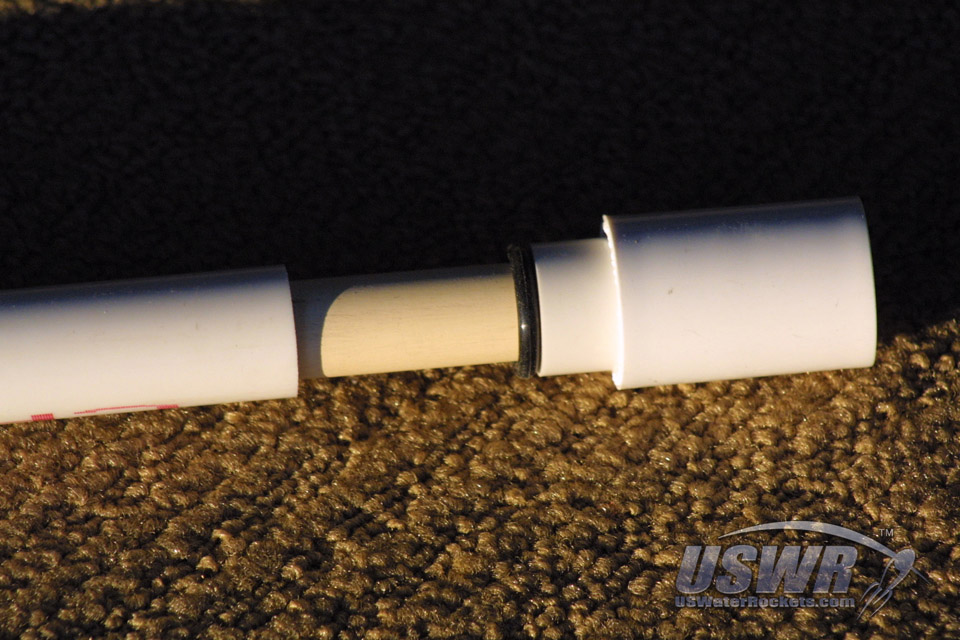
Step 7: Adding the O-Ring seal to the Launch Tube:
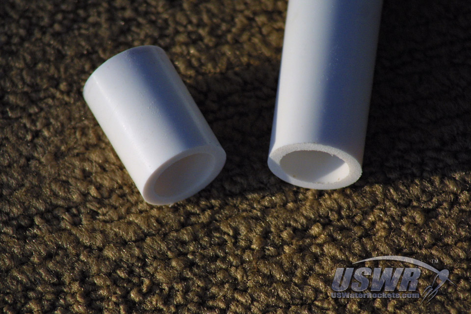
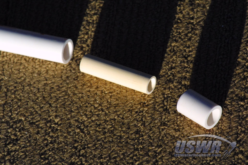
We simply mark the o-ring location about 1/2" from the edge of the female-female coupler. This will be where the O-ring will seat inside the neck of the nozzle. The PVC launch tube is cut off at the mark you just made, and the ends of the cut pieces are sanded as smooth and as flat as you can possibly make them. This will be the sealing surface of the o-ring, so making it as neat and clean as possible is crucial to obtaining a perfect seal. Take the time to make sure these surfaces are perfectly smooth and then move to the next step.The two cut pieces of the launch tube are combined with your 4" section of 3/8" CPVC pipe to create our launch tube o-ring seal. Insert the CPVC inner pipe inside the short piece of 1/2" PVC and glue it in place with PVC cement.
Note:
We have noticed some variation in the inside diameter of the 1/2" PVC pipes which makes inserting the CVPC inner pipe slightly difficult. The PVC cement will act as a lubricant until it begins to cure (after a very short time) so push them together fast or tap them together with a block of wood.
The short piece we have just glued will now be glued inside one end of the PVC 1/2" Female-Female coupler. If possible try and get the glue only on the mating surfaces. Putting on too much glue will cause it to slobber out all over the pipes and will leave stains on the launcher and make it look amateurish.
Slide the o-ring down the CPVC pipe until it reaches the bottom stop at the top of the 1/2" PVC pipe. If the o-ring doesn't slide easily, you can roll it down the pipe. Rolling and sliding will not hurt the o-ring.
Glue the other portion of the launch tube in place on the 3/8" CPVC pipe. Put slight pressure on the O-ring to form a nice seal. Tap or push the tubes together until the tubes touch the o-ring.
Gallery
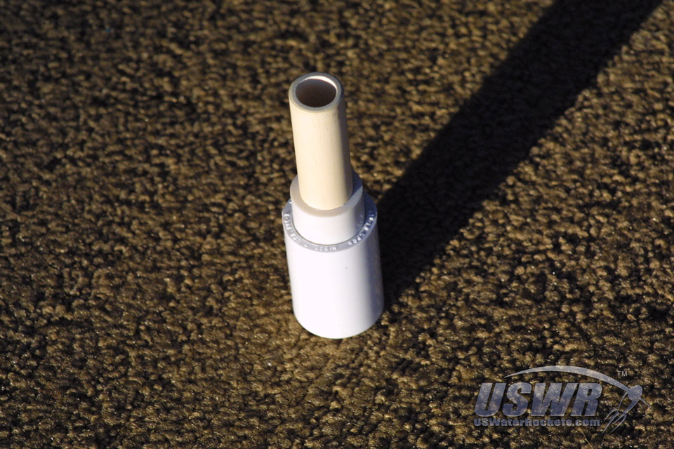

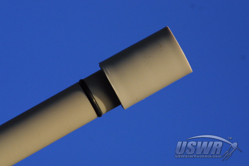
Step 8: Test Fit the O-Ring Launch Tube:
Test fit the newly designed launch tube in your rocket and see how well it fits. You should be able to push the o-ring seal into the nozzle of the rocket with a slight resistance as the o-ring compresses into the nozzle. The seal this o-ring forms is sufficient to seal against more pressure than the bottle is capable of holding. Remember never to exceed the recommended pressures of the pipe pieces you are using to build this launcher. Keep notes of the pressure rating of the parts and rate the launcher for the lowest pressure capable part you have used.Gallery
Step 9: Join the Launch tube to the base tube:
The 4" piece of PVC you have cut will become the interconnection between the base tube and the launch tube as shown. The new section goes between the 1/2" PVC elbow on the base and the 1/2" female-female coupler on the bottom of the launch tube. If you do not plan to color your PVC, you may glue the sections together and allow the glue to cure. When finished, you can slide the Garden Hose washer down the launch tube until it rests on the bottom of the launch tube firmly on top of the female-to-female connector at the bottom. The washer provides a flexible platform on which the nozzle will rest when the rocket is pressurized.Gallery

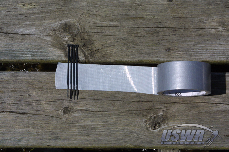
Step 10: Adding the Cable Ties:
Unroll about 8 inches of Duct Tape and place it sticky side up on your work table. Duct Tape is also sometimes referred to as Gaffer's Tape. Then, start placing table ties on the sticky tape, making sure to keep their heads even and the spacing perfectly aligned so the ties are perfectly parallel. Be sure and place the ties onto the tape with the flat side down towards the glue on the tape.Continue to place cable ties one after another until you have enough to wrap completely around the PVC 1/2" Female-Female coupler on the base tube of the launcher. We know from experience that 17 of the ties we use will make one perfectly even wrap around the PVC coupler. If you use larger or smaller cable ties then you may need to test fit and adjust the number of ties. A good method is to put about 4 inches of ties onto the tape and then remove any extras when you go to mount them to the PVC pipes.
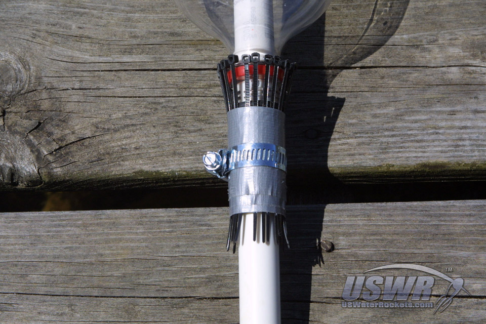
Slide a rocket or a bottle onto the launch tube and push it all the way down to the bottom where it will seat against the hose washer on the Female-Female coupler. Now, carefully take the Cable Tie mounted Duct Tape and place it on the Female-Female coupler as shown below. The heads of the cable ties should just overlap the bottle "grip" protruding from the neck of the bottle. Make sure to wrap the Duct Tape tightly and as evenly as possible.
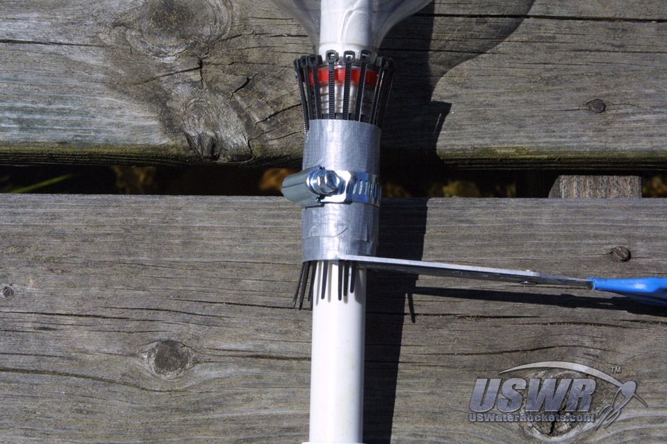
Wrap the remaining tape around the cable ties and cut off the tape with a knife or scissors, then put the hose clamp over the cable ties and temporarily tighten the clamp until the ties are secure and cannot move around. The cable ties should all be perfectly even now and securely held in place by the hose clamp. You can now trim off the excess leads of the cable ties where they protrude from the bottom of the duct tape.
Gallery

Step 11: Sizing and Fabricating the Cable Tie Release Collar:
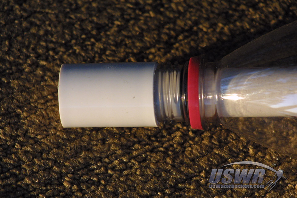
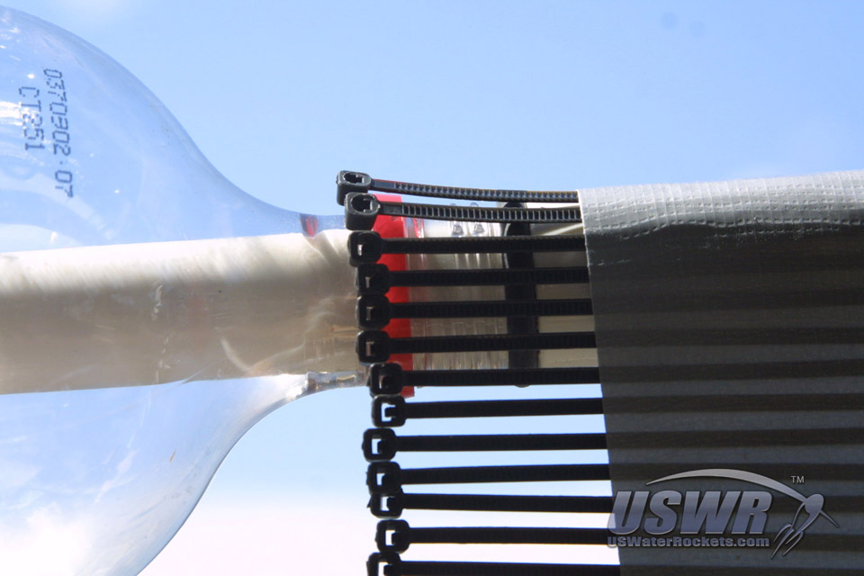
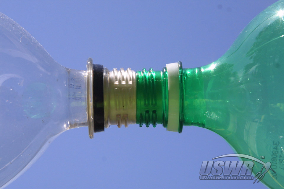
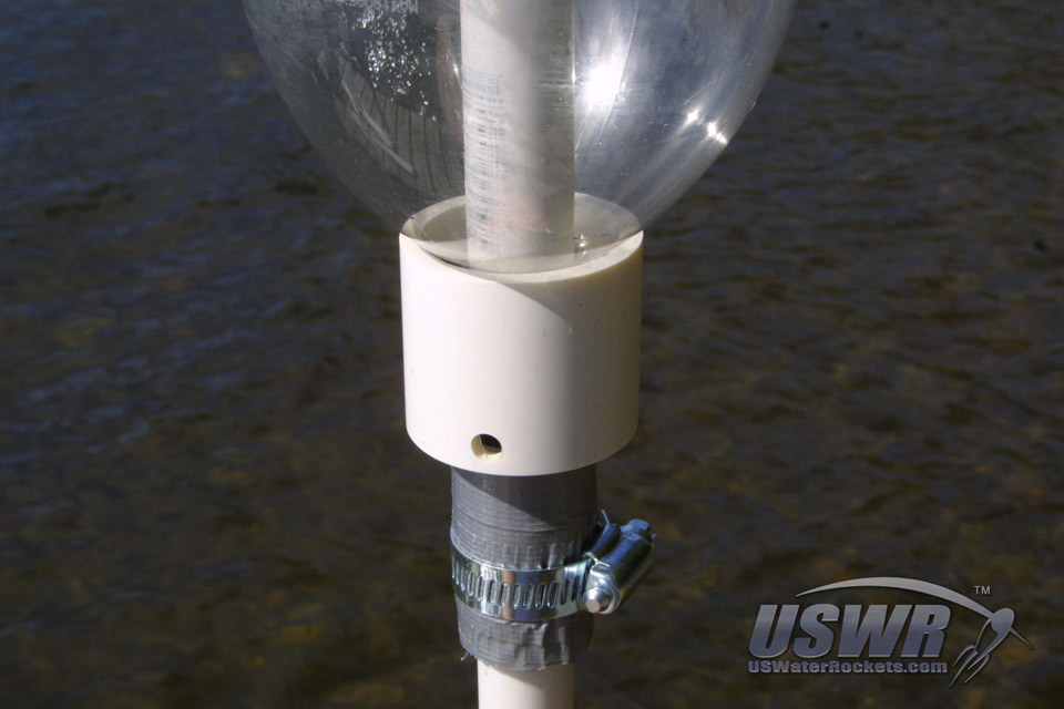
The safety of the launcher depends heavily on this single part, so even if you don't care about the ease of use or the reliability of the o-ring seal, please put the effort into this piece to insure that your rocket is safe and secure on the launcher and will not launch by itself unexpectedly.You will need to decide on the proper diameter for your clamp collar. It is important at this time that you sort out your rocket bottles and decide on a standard bottle to use with this launcher. If you examine your bottles closely, you will discover that some brands of soft-drinks use a different size flange on the neck of their bottles (see image below). The flange is used as the "handle" for the bottle, so it can be gripped by one hand and poured without slipping out of your grasp. Different bottling companies use different size flanges and you will need to decide which size you prefer to use because your launcher will be fitted for one size only.
The critical dimension for your clamp collar is the inside diameter. You will need to find a sturdy plastic tube with the appropriate diameter for your flange diameter. We found that a tube which is 1/8" to 1/10" larger than the flange diameter works extremely well. In our case we use the larger of our two bottle flanges and picked a 1.25" PVC pipe for the tube that will become the clamp collar for our launcher. If you see the image below, you can clearly discern that there is a 1/10" gap between the collar clamp and the flange. This gap will provide clearance for the cable ties to pass through but it is too narrow for the cable tie heads to pass through. This is the proper cable tie launcher setup.
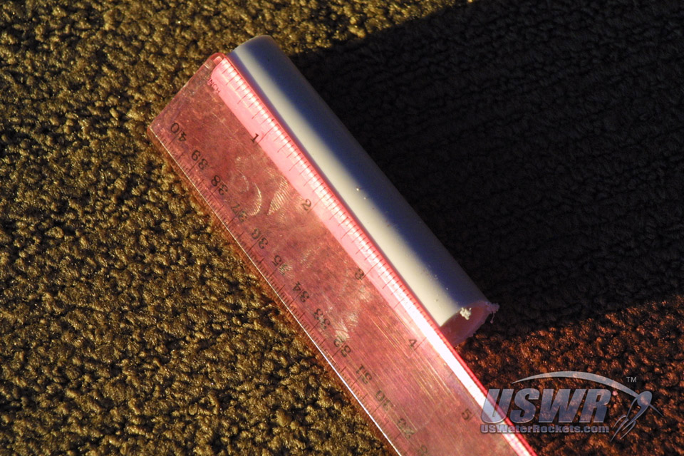
Once you have found the correct diameter tube to form your clamp collar, you may cut the collar to length. The length of the collar is not critical, so we arbitrarily chose a length of 1.5 inches purely for aesthetic reasons. The only real requirement to the length of the collar is to provide a bit of extension below the cable ties when the collar is mounted so that there is room to tie a cable to rope to remotely operate the launcher. The collar should be cut as square and straight as possible because it will seat against the rocket perfectly straight this way and that will make the collar slides smoothly when in use. A crooked collar can bind up and jam or move with more difficulty.
You will now be adding some holes to the collar clamp so that a rope or cable can be attached and operated manually. Drill a hole completely through the collar at the exact center line of the tube. If the holes are not centered or uneven then the clamp will try and twist and could bind up during use. Make sure to drill holes sufficiently large enough to pass through the cable you will want to use.
Tip:
If you are unsure of your ability to drill the holes straight on the first attempt, don't bother to sand the collar tube cut edges until after you have drilled the cable holes. This way if you screw up the holes, you haven't wasted time and effort sanding. Once you get the holes to your satisfaction you can then sand the collar. We simply sanded first because we have done this many times and have the experience for getting the holes straight on the first attempt.
Gallery


Step 12: Testing the Release Collar:
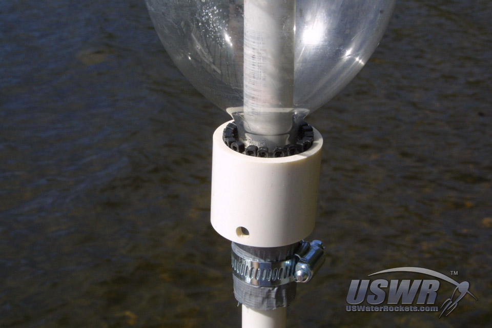
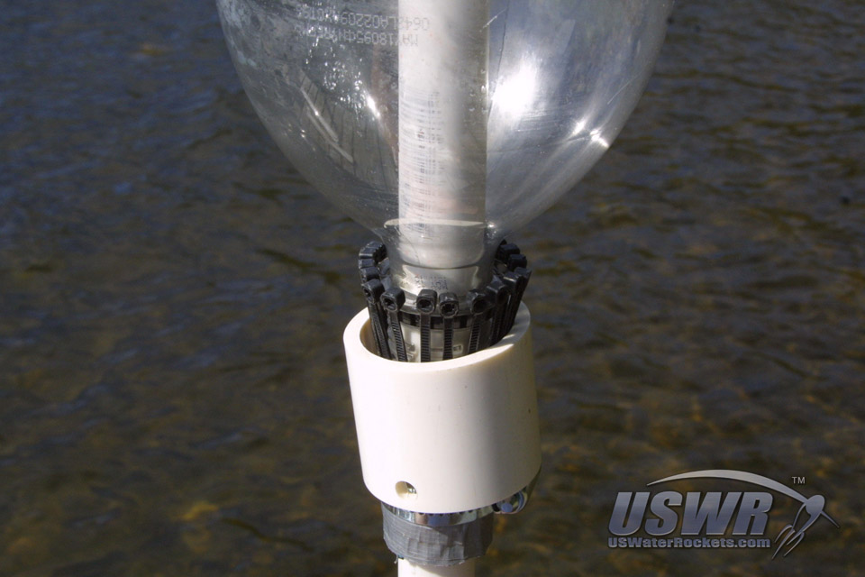
Slide the collar down the top of the launch tube and over the cable ties. If necessary you can grip the ties with one hand and constrict them to allow the collar to pass over them. Slide of bottle down over the launch tube and push it down until it friction fits over the o-ring and seats against the washer on the base of the launch tube. If you have tightened the hose clamp on the bottom of the launcher you will want to loosen it up now so you can adjust it perfectly.With the clamp loose you will move the group of cable ties as a unit up and down until they are overlapping the flange, Push the collar up so that it slides over the heads of the cable ties causing them to constrict around the flange. See the images below for reference and note how the heads of the cable ties overlap the flange and grab hold of it when the collar is pushed up. This is the secret how the launcher operates!
Press down on the bottle so that it is pressing firmly into the washer at the base of the launcher. The harder you press the better the secondary seal at the base washer will be. While keeping the pressure on the bottle, pull the cable ties assembly tightly down away from the flange as hard as you can pull and then tighten the hose clamp to secure the cable ties in this position. Be sure to leave enough room between the hose clamp and the bottom of the clamp collar so that it can move down all the way off the nozzle when it operates. The collar usually cannot pass over the clamp so you need to provide some distance for it to operate. You should try to get 0.75" to 1.0" between the top of the clamp collar and the bottom of the flange on the bottle when the clamp collar is fully retracted.
Practice operating the clamp a few times and see how it works. It should push all the way up against the rocket and sit neatly and squarely on the bottom of the bottle. It should slide easily down the cable ties and come to a stop against the hose clamp at the bottom with enough room for the cable ties to expand around the flange and allow the bottle to slide off the o-ring and up the launch tube. Push the rocket back onto the launch tube and allow the cable ties to surround the flange as the o-ring seals inside the neck. Push up firmly on the collar and notice the tension of the cable ties pulling taught against the flange causes the bottle to seat snugly against the washer at the base of the launch tube. That's perfect!
Gallery
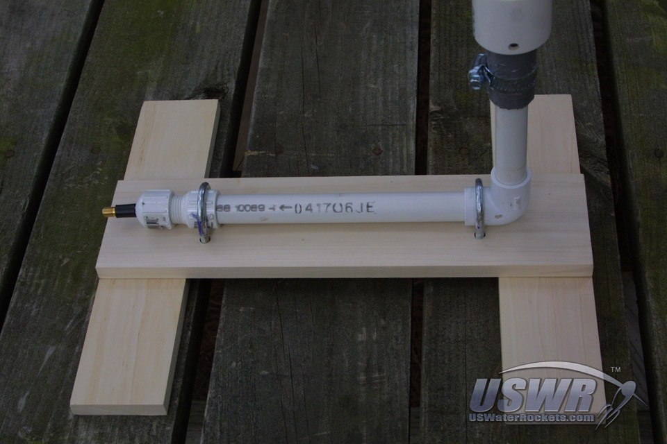
Step 13: Building the Launcher Base:
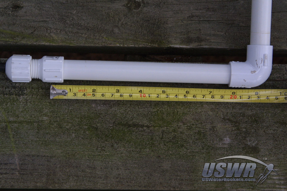
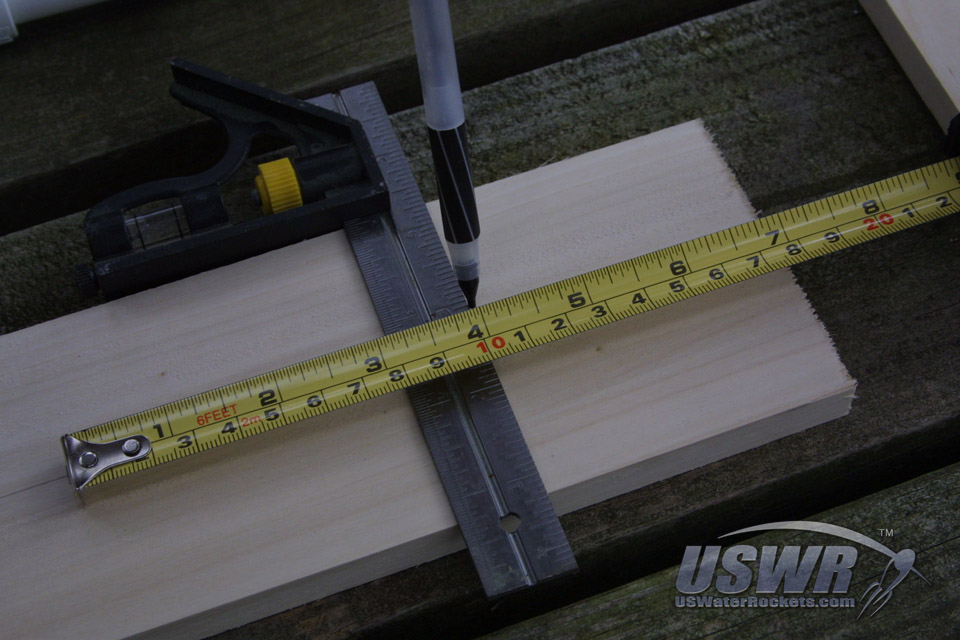
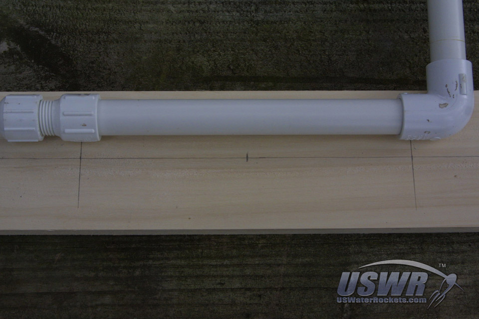
The base is made from a main spar of the base with a perpendicular spar on each end, forming legs. The main spar will be the main structure which the other parts will attach. The length of the body must be created so that it is long enough to accommodate the legs of the launcher and still allow clearance for the mounting hardware. If you neglect to leave room for the hardware you will find yourself with a launcher you cannot assemble because the holes you made for the U-bolts are underneath the place the legs are attached.The distance between the U-bolts is actually the same length as the PVC pipe at the bottom of the launcher plumbing. This length places the U-bolts right over the PVC fittings on either end of the pipe. In our case we have 8" for the distance. You can use any place on the fittings that places the U-bolts in a secure location and measure that distance to determine the U-bolt spacing. Make a note of the number.
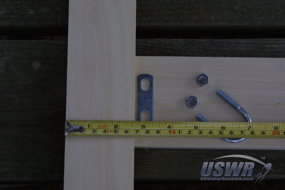
For our design, we measured the width of our launcher leg boards plus some extra spacing to allow for the nuts and mounting plate of the U-bolts. We simply set them in their rough positions and measured the space required. Since these dimensions are not critical, we rounded up to the nearest inch and came up with 3 inches of space required for each leg. We added the board length needed for 2 legs plus the length needed for the PVC tube which is 3"+3"+8", giving us 14" for our main body length. If this is too much detail work, you can just cut the legs to a reasonable size and then simply take the leg pieces and mock up the launcher in the final configuration and with the parts placed together like this you can make a mark on the main spar which will give a rough estimate of the correct length.
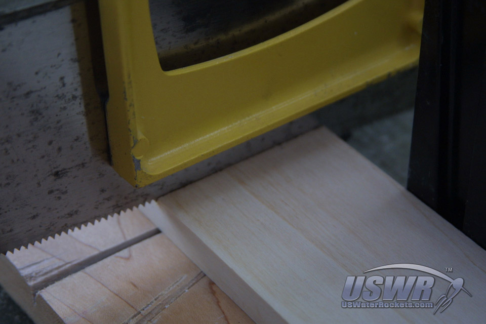
We marked out a 14" length of 1/2"x4" board for the main body spar of the base, and for our legs we used 1/2"x3" board. For the length of the legs, we picked an arbitrary length of 12". This length means one 4' board would yield four complete legs. There is nothing special about the length of the legs. A rule of thumb would be to make sure it's not shorter than 50% of the main body length. This will insure the legs are wide enough to be stable.
Notice that we have used a small carpenter's square to insure that our lines are all at perfect 90 degree angles. We want to try and make our cuts as square as possible when we make them. This only serves to make the launcher look more professional and really isn't critical to the operation in any way. How hard you work on the cosmetics is entirely up to you. You may want to put the effort into making a neat cut now because we will be giving tips on how to customize and dress up the launcher in the future and a neat job here will pay off handsomely then.
We now have the two legs and the main body board cut and ready for more work. Bear in mind that these proportions and board sizes are not very critical, and we picked the dimensions we did for reasons of aesthetics as well as to try and optimize the number of launcher pieces we could make using standard board lengths found in our local store. Please feel free to tweak the sizes to whatever suits your needs.
Gallery

Step 14: Locate and mark the U-Bolt Holes:
Find the center line of the main body spar of the base. The easiest way to do that is to measure the width of the board and divide by two and then mark this width near each end of the board and use a ruler or some other straight edge to draw a line the length of the board making the center line. This mark will insure that the launcher turns out perfectly symmetrical when finished. If you have a calibrated eyeball you can visually locate the center line of the board. Find the center point of our main launcher body board, using the same method. Put a mark on the center line we just made at the point 1/2 of the length. This will give the exact center of the board and will insure the pipes are mounted in a nice symmetric way.The location of the U-bolts is trivial math, because we took care in the earlier steps. Remember the length of the main PVC pipe at the bottom of the launcher? Well, we will be using that length now to precisely locate our U-Bolt holes.
Starting at the center point we marked on the base board, we will measure along the center line to locate the U-Bolt locations. The locations we want are exactly half the length of the PVC pipe which we recorded earlier. In our case we had an 8 inch long pipe, so we mark the board 4 inches from the center point on moth ends. We use our carpenter's square to make a line where each U-bolt will go. This line will be the center of the drilled holes for each U-Bolt, so we want to make the line as straight as possible and at a right angle to the board.
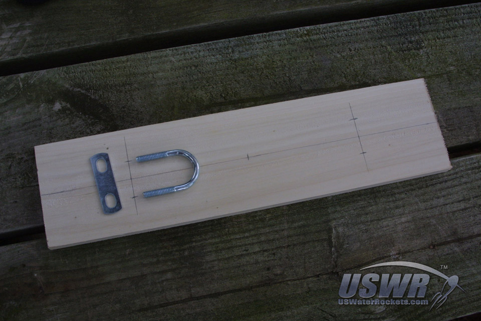
When finished making both locations for the U-Bolts, you can check your work by measuring the distance of each U-bolt from the end of the board closest to the spot. The two measurements should be equal. In out case our U-Bolts are each 3 inches from either end. If we were to place the 1/2"x3" plank we want to use for the legs on either end of the board we can also test that the holes are not going to interfere with the mounting of the legs.
To locate the holes for the U-Bolts on the lines we just drew, we will simply measure the width of the U-Bolts and divide by 2. This will result in the distance from the Main body board center line we must mark out on each of the drill lines we just made.
We now can measure the distance for each side of the U-Bolt along the drill lines and mark the positions. These locations are the places where we will be drilling holes for our U-Bolts. Carefully mark each hole location on the drill line for each end of the board. This will produce the hole locations we need for the two U-Bolts. Check your work by laying a U-Bolt on the board next to the drill marks we just made and verify that the drill marks really do line up with the tips of the threaded parts of the U-Bolt.
Gallery


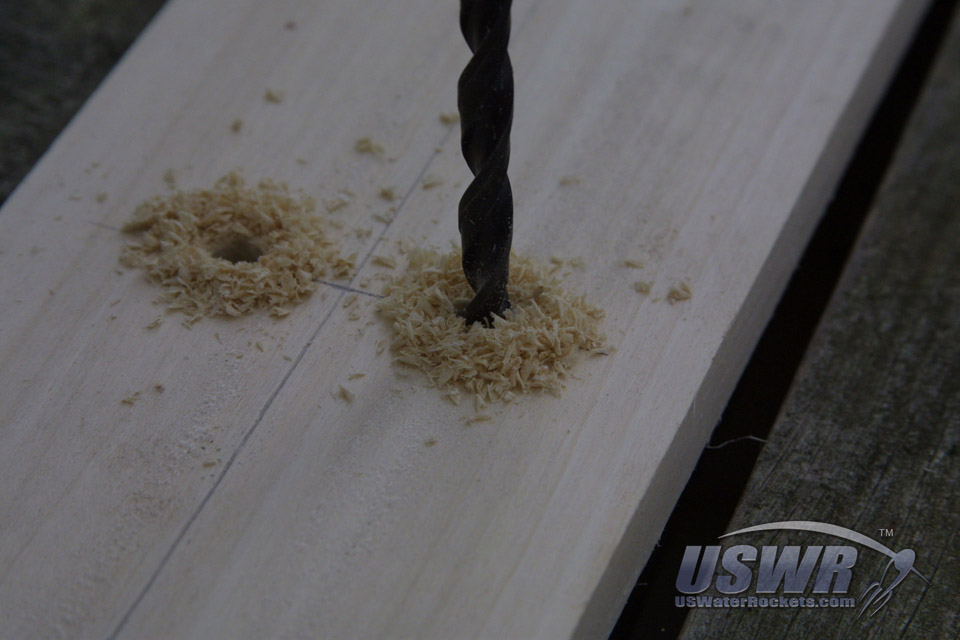
Step 15: Drill holes for the U-Bolts:
Our U-Bolts have take 1/4" nuts, so we want to make sure we drill the holes that are large enough to accept the U-Bolts. We picked a 5/16" drill bit so that our holes will have 1/16" tolerance. If you think you will not be able to drill your holes with that much accuracy, you can pick a larger drill bit which will give you some additional tolerance.Loosely install the U-Bolts in the holes, and make sure everything fits properly. It's a good idea to put everything together in this way to look for possible problems with clearance or alignment issues. If necessary, you can drill out the holes you just made a bit larger with the next larger size drill bit if you have overestimated the accuracy of your drilling skills.
Gallery
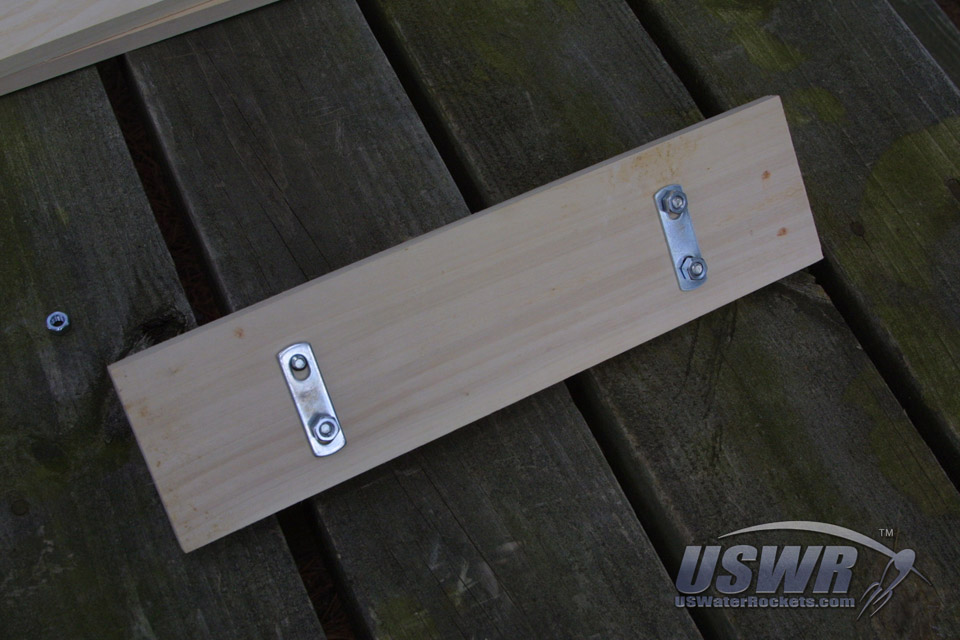
Step 16: Adding Legs to the Base:
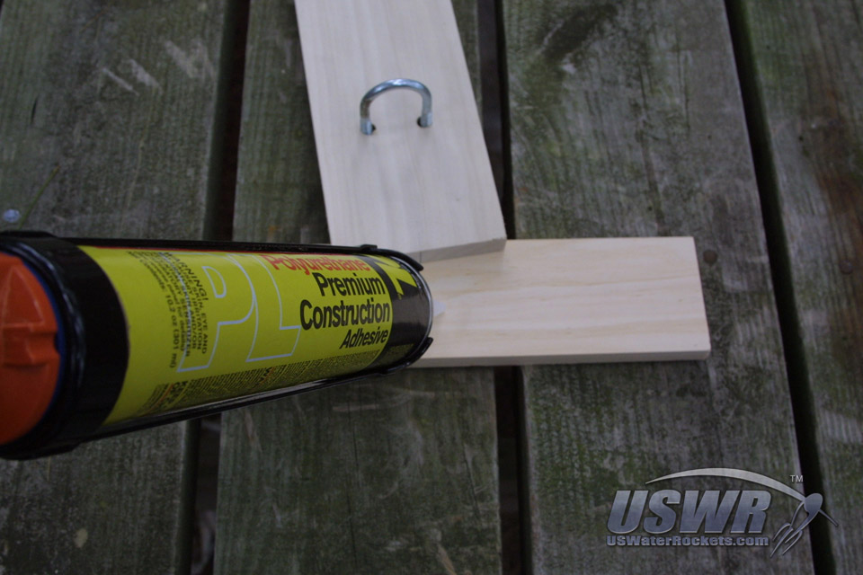
Measure the length of the leg boards and divide this by 2 to determine the center point of the legs. This will be aligned with the center of the ends of the main spar. Place marks on the boards so you can assemble them accurately. It's best to sand the base board now because the legs will be attached next and this will make sanding the boards a lot harder.There are countless methods of connecting these boards together. You can screw them together or nail them. These are the fastest and easiest methods, but we have found that they have problems. Nails and steel screws tend to rust, and that can leave a stain and look messy. Nails and screws are also prone to working loose under use. Our preferred method of connecting the legs to the main base board is to use glue. Of course the best glue for all things water-rocket happens to be PL Premium Polyurethane! We put a small amount on each leg where it attaches, and put the main base board on top.
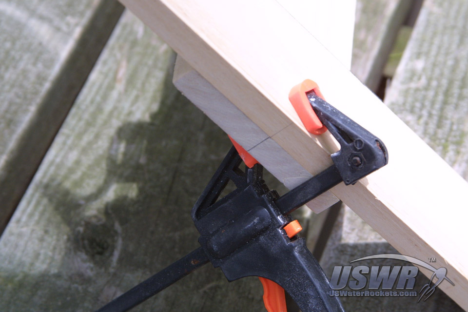
We assemble each of the legs onto the base the same way, using a clamp to hold the boards firmly together until the glue has cured. If you have clamps like ours with rubber pads to protect your work, you don't really need to take any special precautions. if, however, you have metal faced clamps then you will want to put some scraps of wood under each contact point to protect your wood from getting marred or dented by the clamps.
Before you fully tighten your clamps, make sure the center markings on each leg line up perfectly with the center line markings on the ends of the main base board. Also make sure to use a square or right angle of some form to check that the legs are at a perfect right angle to the main base board. Tap the wood with a block of wood or the palm of your hand until you have it perfectly lines up and tighten the clamp fully. Don't over-tighten!
After the glue has fully cured, you can remove the clamps. You may want to sand off the center line marks and when you have finished beautifying your launcher you can then mount the plumbing loosely on the top of the launcher with the U-Bolts.
Gallery


Step 17: Installing the remote release lanyard:
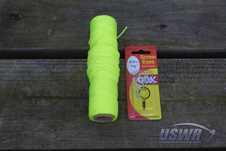
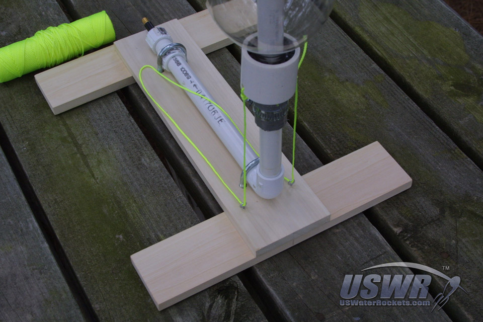
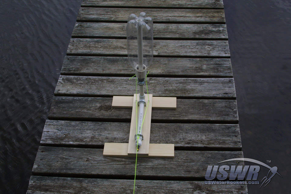
A remote release mechanism is necessary because we are working with pressurized air inside a plastic container which could burst and cause injury (possibly severe). You will need to be able to operate your launcher to fire the rocket from a safe distance. Whether you plan on holding your own friendly competition or choose to compete internationally with water rockets around the globe in the WRA2 record competitions, you will need to abide by a water rocket safety code which will specify the minimum safe distance you need to be from the rocket.For our design, we are using a very simple and easy to fabricate release mechanism controlled by a lanyard made from carpenters string. The parts we need to obtain are some screw eyes and some strong string. We chose this fluorescent yellow string because of it's obvious high visibility. This is a safety feature to help prevent someone from accidentally tripping over the string and launching their rocket by mistake.
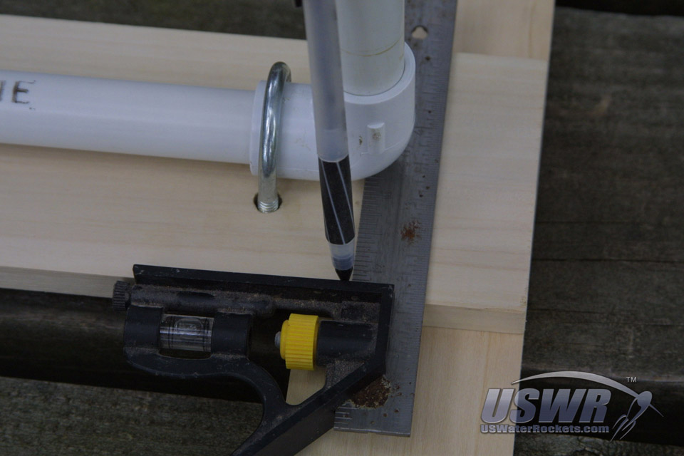
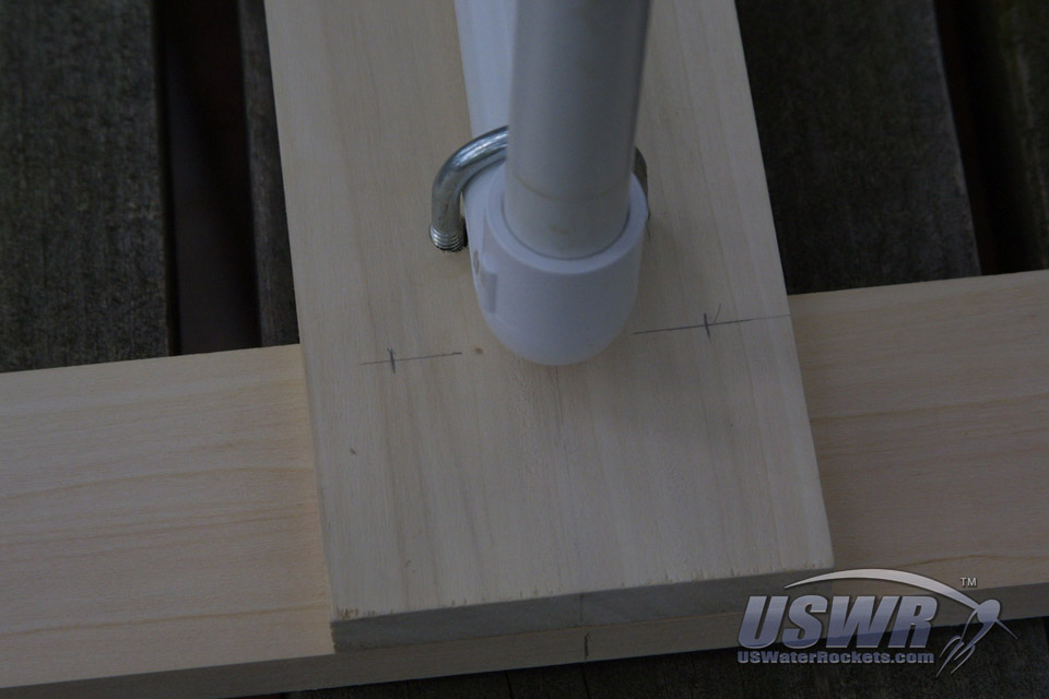
To help align our screw eyes, we are using our square to draw a line along the center line of the launch tube. Fortunately for us, there is a mold line exactly bisecting the 90 degree elbow at the base of our launcher, so we just lined our square up with the mold line and drew our line at the center of the launch tube onto the base board. If you don't have a mold line you can use your eye to estimate where the line should be or measure to find the location of the center of the launch tube and draw your line there. Mark some eye locations along the line we just drew. Make sure that the eyes were spaced farther apart than the width of the U-bolts so that the release string does not rub on them.
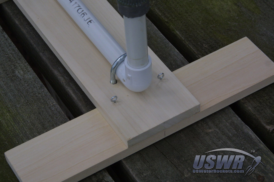
Use a small drill to make some pilot holes in the wood to insure the screw eyes were in the right spot and could not go in crooked from hitting the grain of the wood. It's always a good idea to make a pilot hole when screwing material together like this.
Measure out about three feet of the release string and fasten it to one side of the release collar. The other end of the string will feed through the eyelet on the side of the launcher which will face away from the operator and cross over to the screw eye on the opposite side of the launcher and back into the other eyelet from the side facing the operator to the back side and up to the hole in the opposite side of the release collar. Tie the release string onto the collar at this spot.
The remaining roll of release string will tie onto the piece we just connected to the launcher forming a "Y" shaped pull string. You will want to tie the main roll of string in a knot that can slide freely from side to side in such a way that it will center itself when pulled tight and will pull evenly on each side of the launcher.
Gallery


Step 18: Adding Legs to the Base:
When you are finished, you can now give the launcher a quick test. Push the collar up onto the nozzle of the bottle and see that a yank on the release string will pull if off the nozzle without any trouble.If you sense a lot of resistance you can apply some cooking oil spray to the cable ties and this will lubricate them so they slide freely. You may wish to apply some lubricant now regardless because you may want to launch some high pressure rockets and the lubricant will help release them with higher pressure inside, as the pressure can increase the friction of the collar.
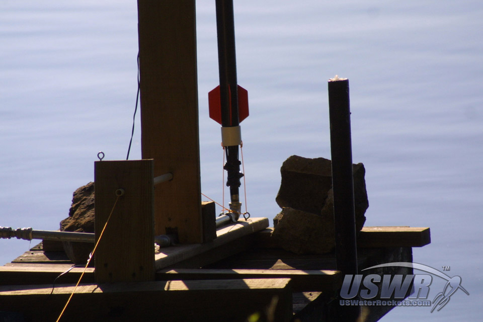
At this point you can take your launcher and start flying! Congratulations!!!
Gallery
 Water Rocket Cable Tie Launcher by
U.S. Water Rockets is licensed under a Creative Commons Attribution-NonCommercial 3.0 Unported License.
Water Rocket Cable Tie Launcher by
U.S. Water Rockets is licensed under a Creative Commons Attribution-NonCommercial 3.0 Unported License.