


How to construct a Water Rocket Radial Parachute Deploy Mechanism
Introduction:
Much of our ongoing research focuses on refining and improving water rocket systems to make them more reliable and easier to build. One area in which we have spent a great deal of time is the water rocket parachute deploy system, since it is the key to safely recovering a rocket and payload and all the time, materials, and labor that went into building them. To insure the safe recovery of our fragile and expensive experiments and payloads, we decided that we needed to invent a parachute system that was more reliable than anything ever flown before.We dubbed this new design the "U.S. Water Rockets Radial Parachute Deployment System", and it is a radical departure from traditional systems, because it relies on only one moving part. The system we designed met that goal and also has a number of other advantages over previous systems:
- Lower cost thanks to less materials needed.
- Takes far less time to build.
- Can be located in different positions on a rocket for use as primary or redundant parachute.
Table of Contents:
ConstructionArming the Deploy
How it works
Modifications
Video
Related Tutorials:
Building the Radial Deploy System:
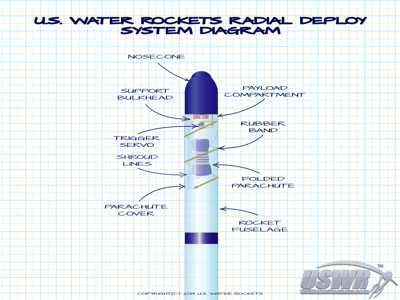
This tutorial explains how to make the Radial Deploy System, and how it works. For simplicity we will show how the system is added to the top of a rocket since that is the method the majority of users will employ, but we will explain how to place the Radial Deploy System at different places on the rocket at the end of this tutorial in the "Modifications" section. Consult the diagram at the top of this tutorial to see the location of the various components as you construct your own Radial Deploy System. ...Gallery

Step 1: Make the payload compartment for the trigger mechanism.
The payload compartment will contain the release mechanism that triggers the parachute system, and will typically be connected to the top of the rocket. The payload compartment is made by cutting a bottle in half and then turning it over so the neck is at the bottom.The cut edge of the payload compartment can optionally be curled inward to give it some strength and makes sliding the nosecone off the top easier.
Gallery
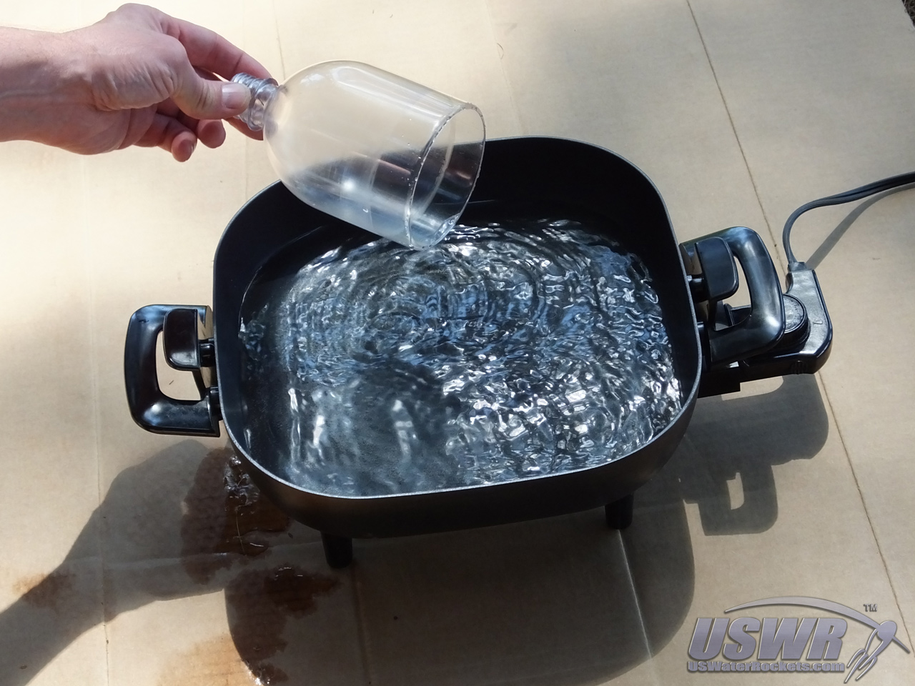
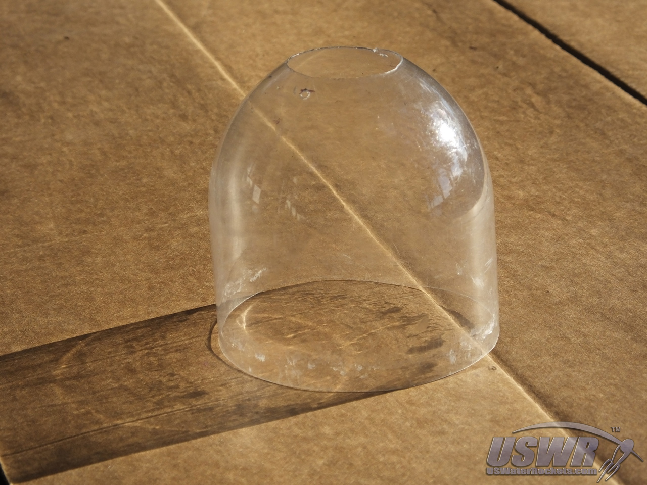
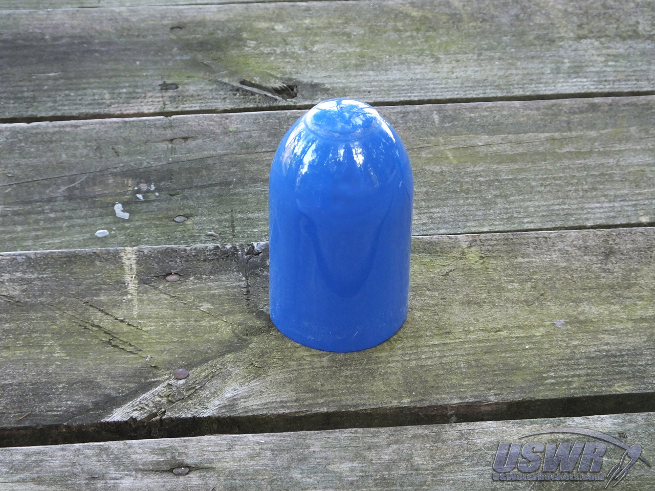
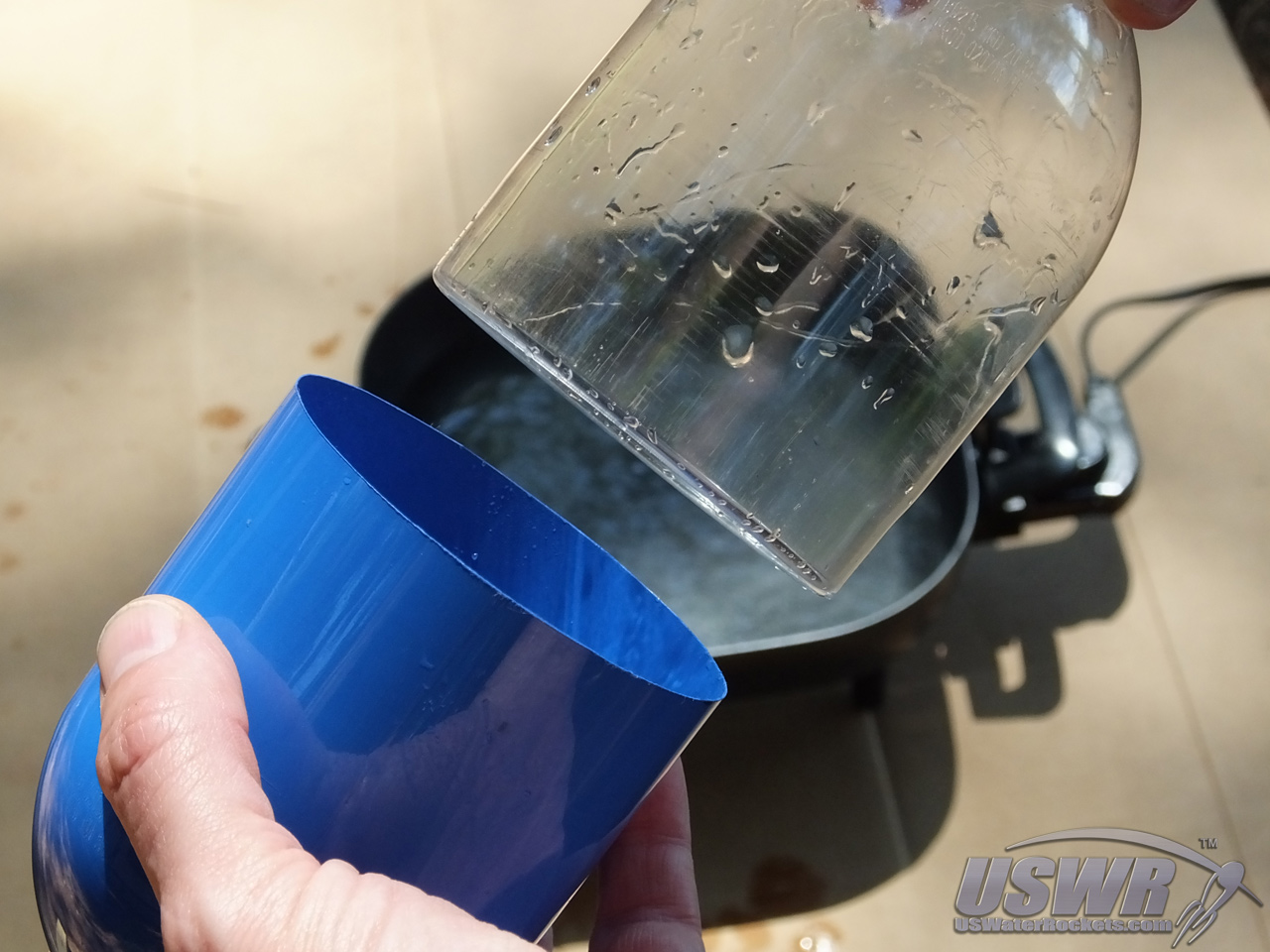
Step 2: Make a nosecone for the open end of the payload compartment.
To make a nosecone, you will need to cut the neck off a second bottle and slide it over the open end of the payload compartment. For improved aerodynamics, you can cut the threaded part off the top of the nosecone and cover the hole with a plug cut from a plastic ball or egg.Gallery
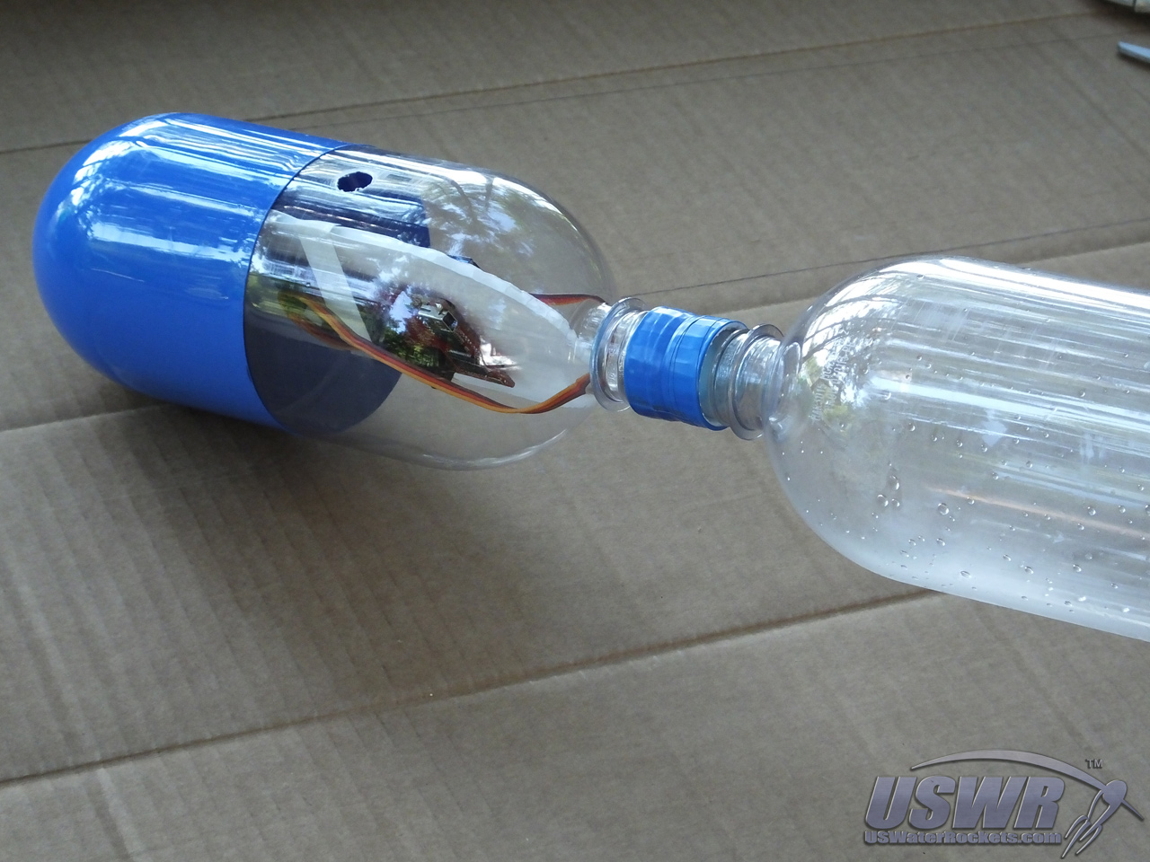
Step 3: Make a coupler to connect the payload Compartment to the top of the Rocket.
A very easy way to attach the Payload Compartment to the top of the rocket is to tape two bottle caps together back to back and screw one side of the double cap into the bottom of the payload compartment, and the other side into the top of the rocket.If the tip of your rocket is currently the foot of a bottle, you will need to cut the neck off another bottle and slide it over the top of your rocket so that the top of the rocket is now the threaded portion of the cut bottle. Tape the cut bottle securely to the foot at the top of the rocket.
Gallery


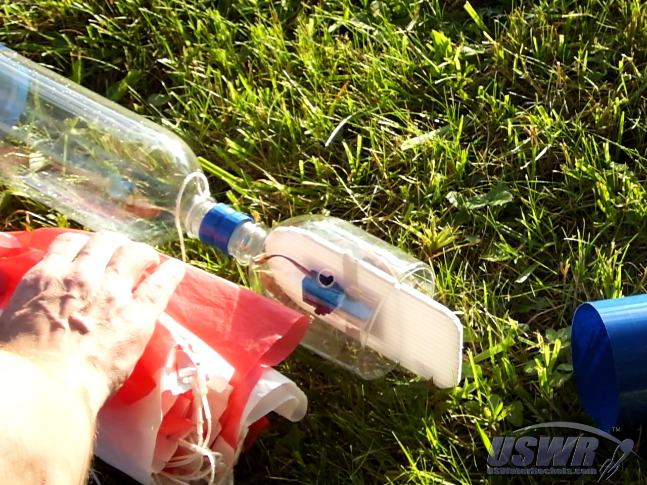
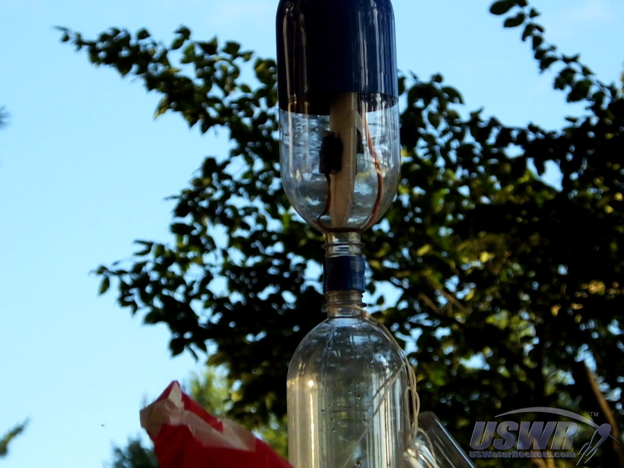
Step 4: Make a support bulkhead for your trigger mechanism.
A place to mount the trigger mechanism inside the payload compartment is made next. You can cut it from a piece of corriflute or balsa wood, or even cardboard. The purpose of the bulkhead is to provide a support structure for the release mechanism, so your design will depend on the shape of you payload compartment and the trigger you use.In our example, we are using a ServoChron™ Servo Timer, which you can build yourself following these plans on our website: [ServoChron™ Manual]. We attach the ServoChron™ and the release servo motor to the bulkhead using Velcro, tape, or cable ties. You will need to adapt this operation to the exact mechanism you use.
Gallery

You can potentially omit the bulkhead component if you connect the trigger mechanism directly to the walls of your payload compartment, similar to the way we mounted these items in our Axial Deploy System tutorial [Axial Deploy Tutorial].
Gallery

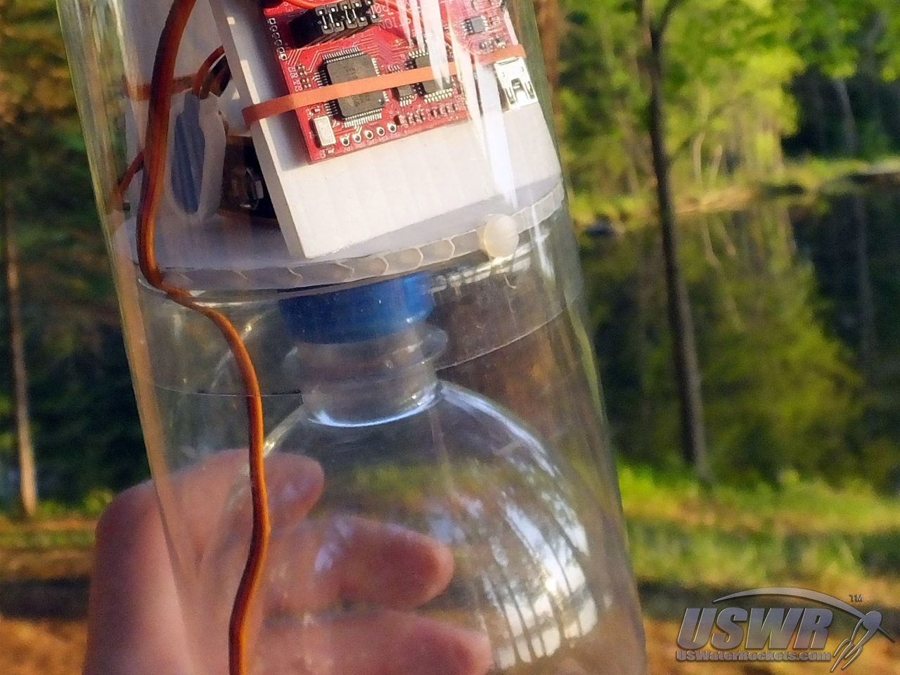
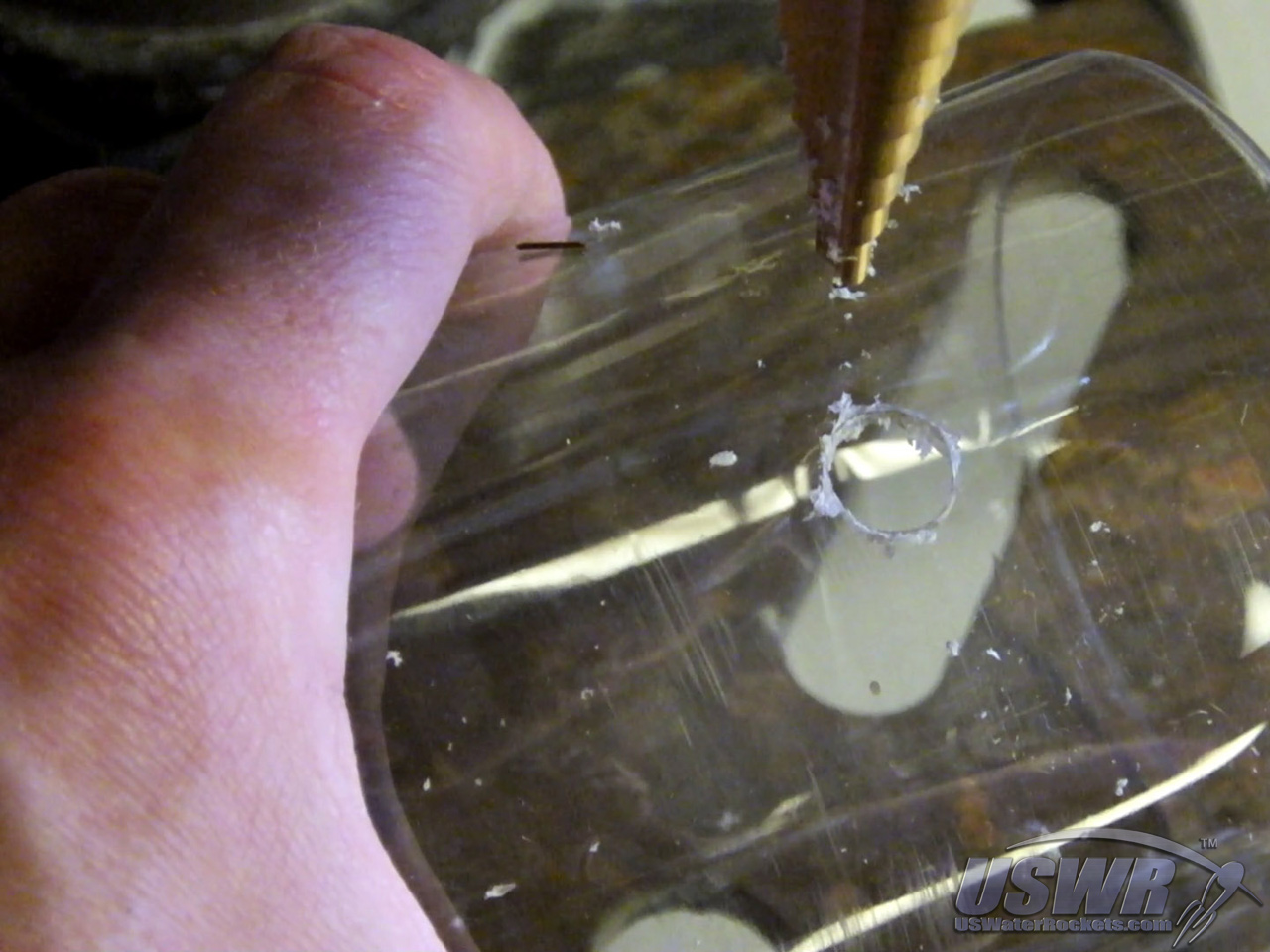
Step 5: Make any necessary access holes in the payload compartment.
If your trigger mechanism needs to be armed or powered on in some manner, you can now make any necessary holes in the payload compartment that will provide access from outside so it can be manipulated. This is the best time to make these holes, since the support bulkhead is now in place and it is very easy to locate where you need to place any access holes and cut or drill them. You can now assemble the Payload Compartment to the rocket and put the nosecone on.Gallery

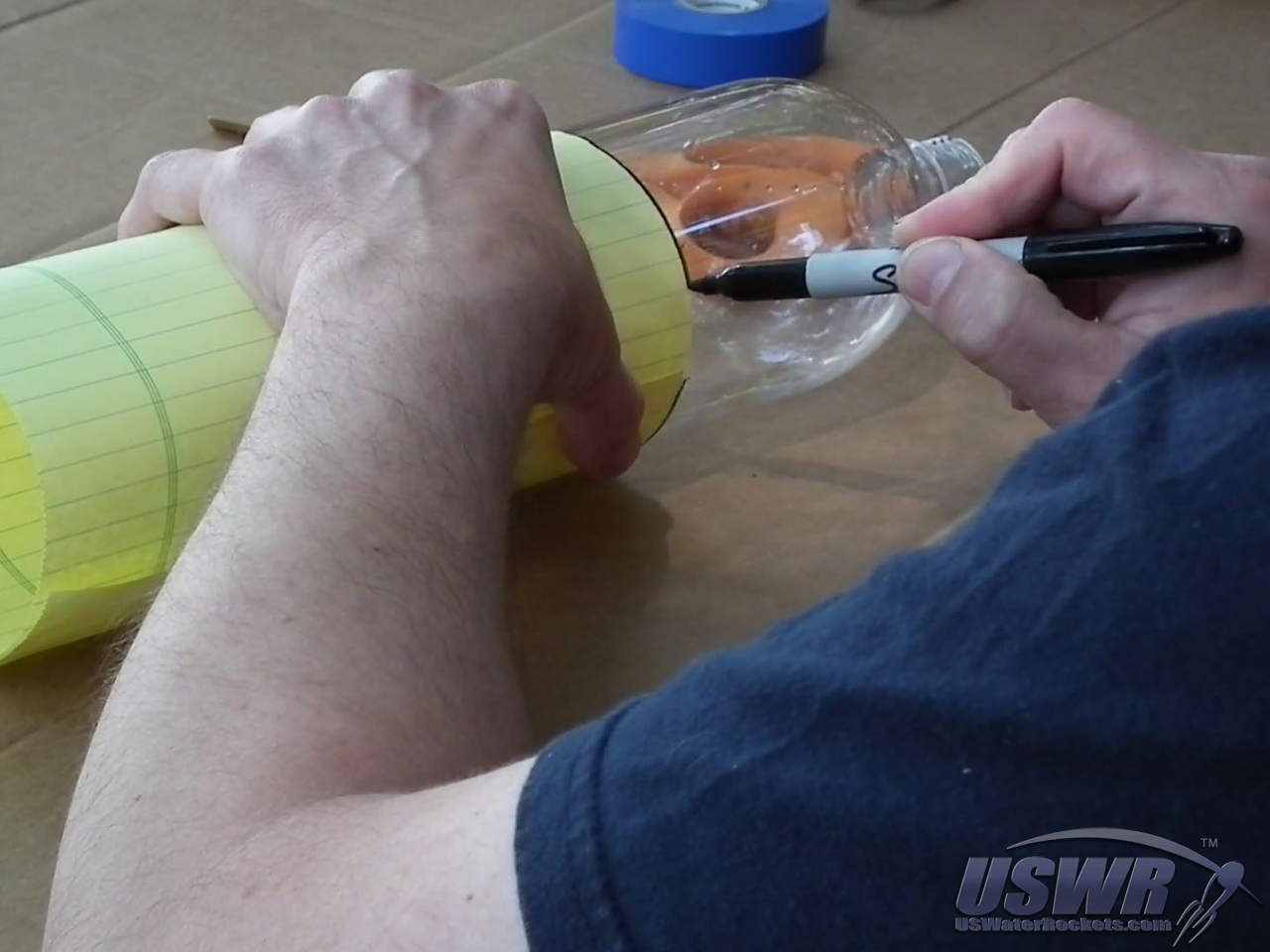
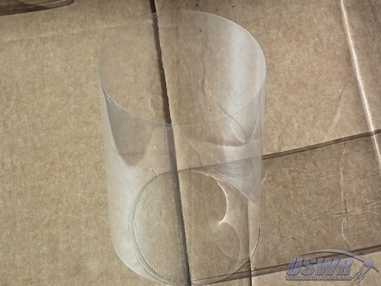
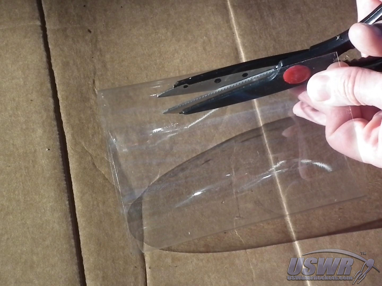
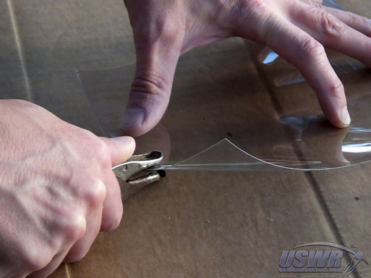
Step 6: Constructing the parachute cover:
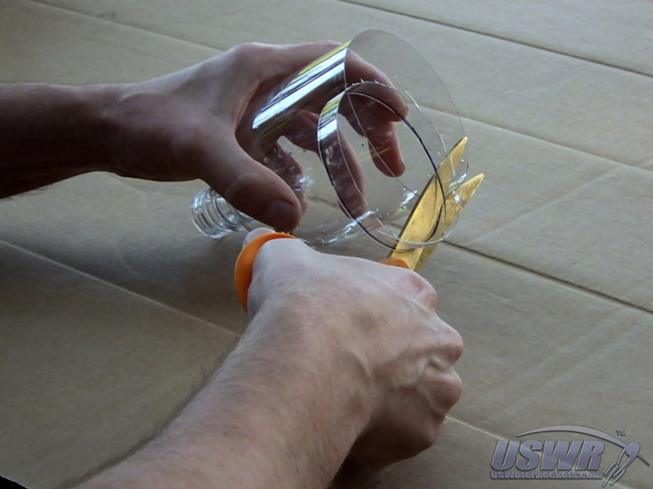
The parachute cover is made from a bottle with the neck and foot cut off, leaving a cylindrical sheet of plastic that is then sliced vertically and flattened out. The parachute cover is best made from a bottle that is larger in diameter than the bottles you made your rocket from, because when the parachute cover is wrapped around the rocket it must overlap itself about 1 inch (2.5cm).Gallery

The parachute cover must be long enough to bridge the gap between the two bottles with at least 1 inch (2.5cm) of contact area against the bottles above and below the bottle necks. If you do not have enough contact area, the parachute cover becomes tricky to align.
If you cannot find a bottle large enough to make a parachute cover from that will meet these requirements, you can always make the parachute cover from several flattened bottle sections glued together to make them bigger.
Gallery
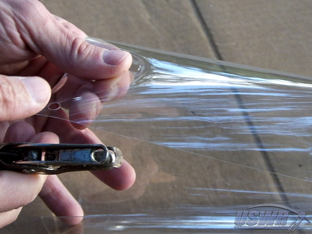
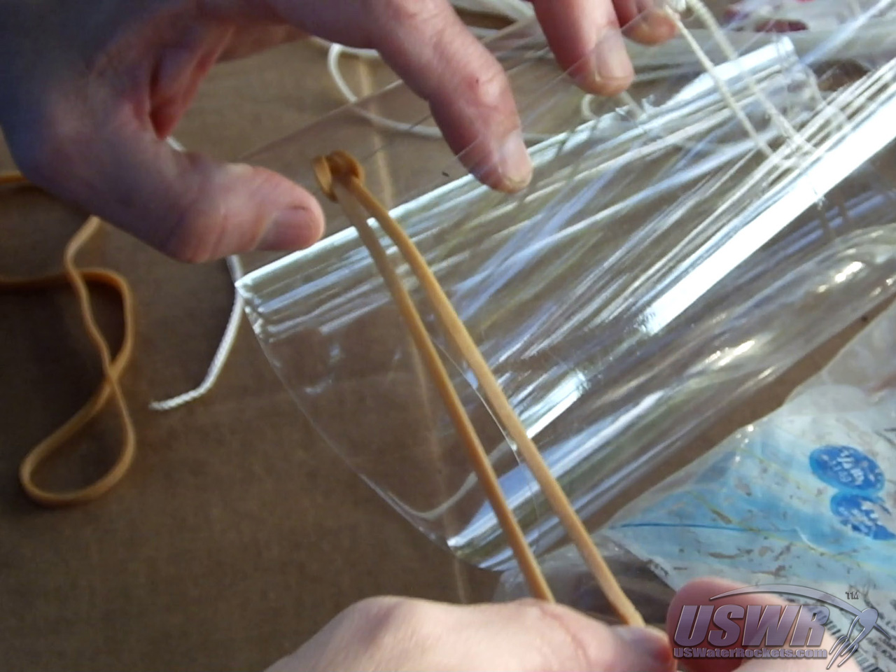
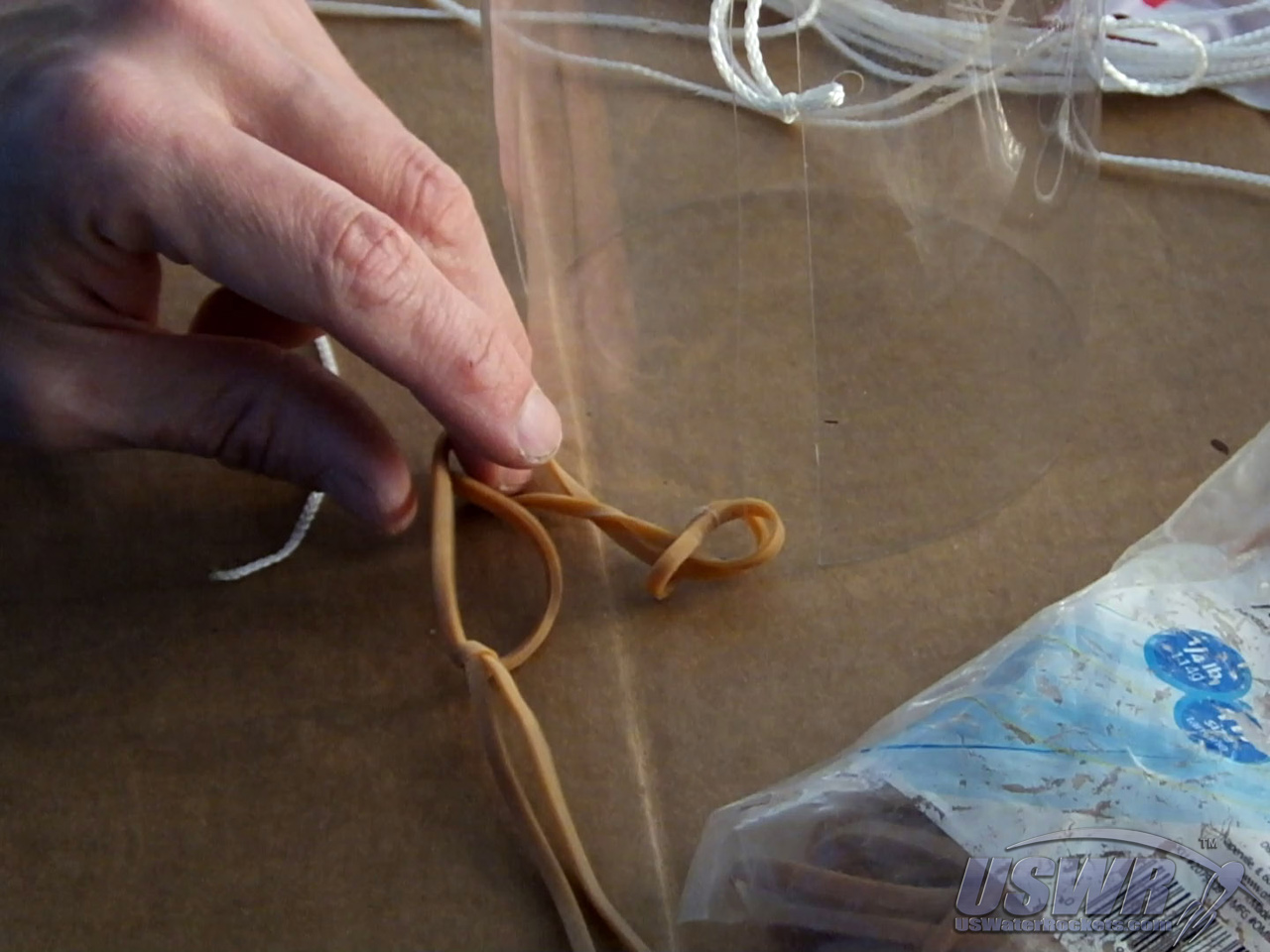
Step 7: Attach the rubber band(s).
A long rubber band is tied to the hole in the corner of the parachute cover. The length of this rubber band will vary depending on the diameter of the rocket size, but you can easily add additional rubber bands by linking them together to adjust the length as necessary.Gallery

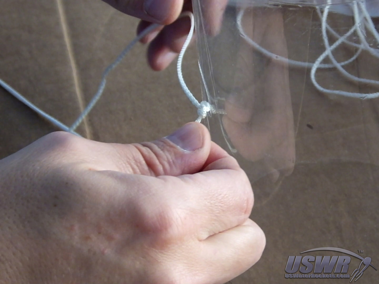
Step 8: Attach the parachute.
The main shroud line of your parachute should be at least 3 feet in length (1 meter) and you will tie the very end of it to the bottle neck at the top of the rocket. Make sure to secure it well, because the entire weight of the rocket will be on this connection.Find the midpoint of the main shroud line and tie this to the parachute cover at the remaining hole. This connection helps pull the parachute out of the rocket and also retains the parachute cover from flying away after it comes off.
The construction of the radial Deploy is now complete. The following sections deal with the way the system is armed and how it works.
Gallery

Arming the Radial Deploy System:
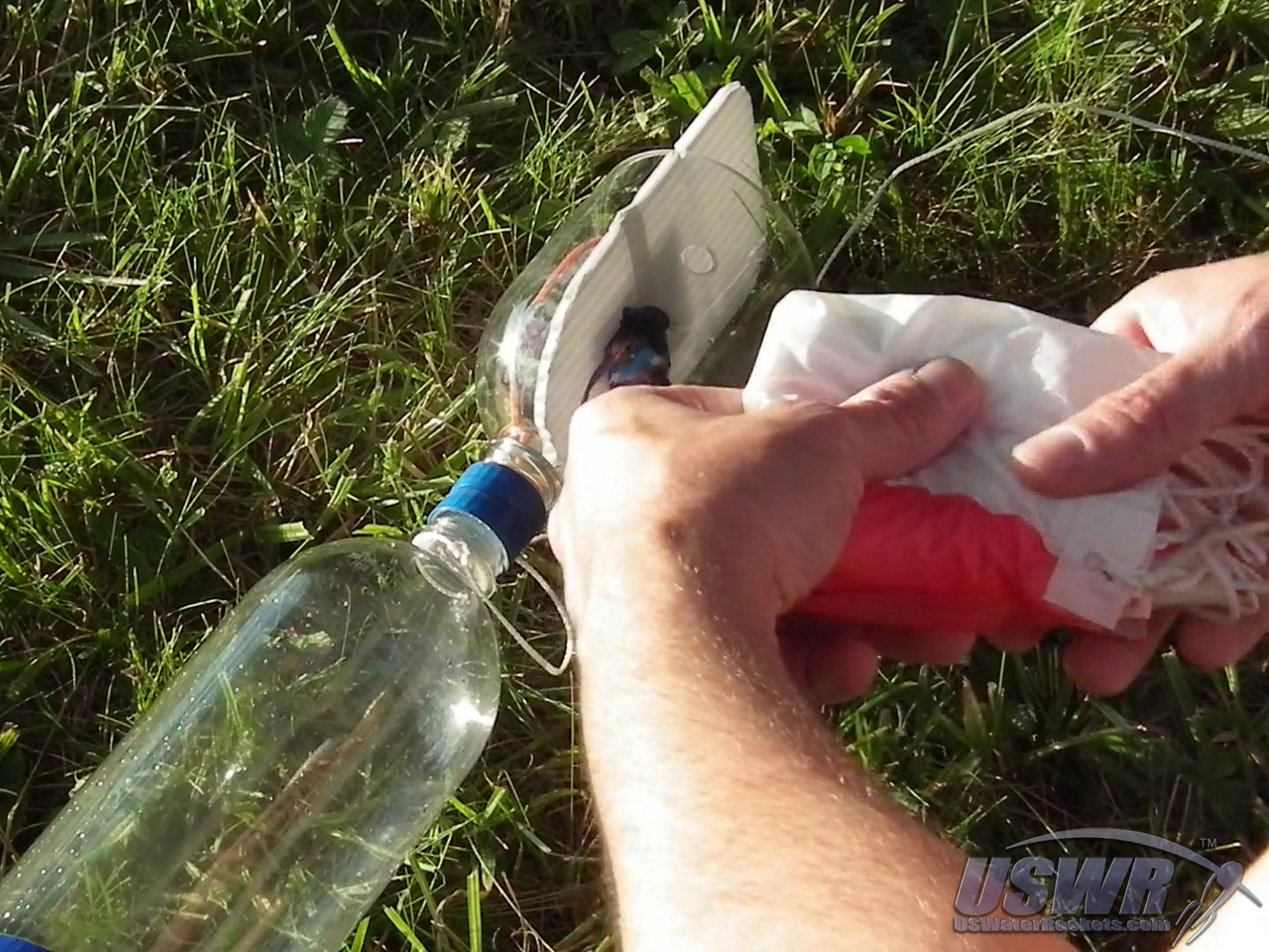
A few steps are needed to arm the Radial Deploy System to insure a successful parachute recovery. Follow the directions below to insure that you have the best possible results.Step 1: Folding the parachute:
Take the parachute and fold it however you prefer, It will function better if you fold it loosely and avoid compressing it into a tight wad. Once folded, you can stow the parachute in the narrow area where the payload compartment screws to the top of the rocket.Gallery
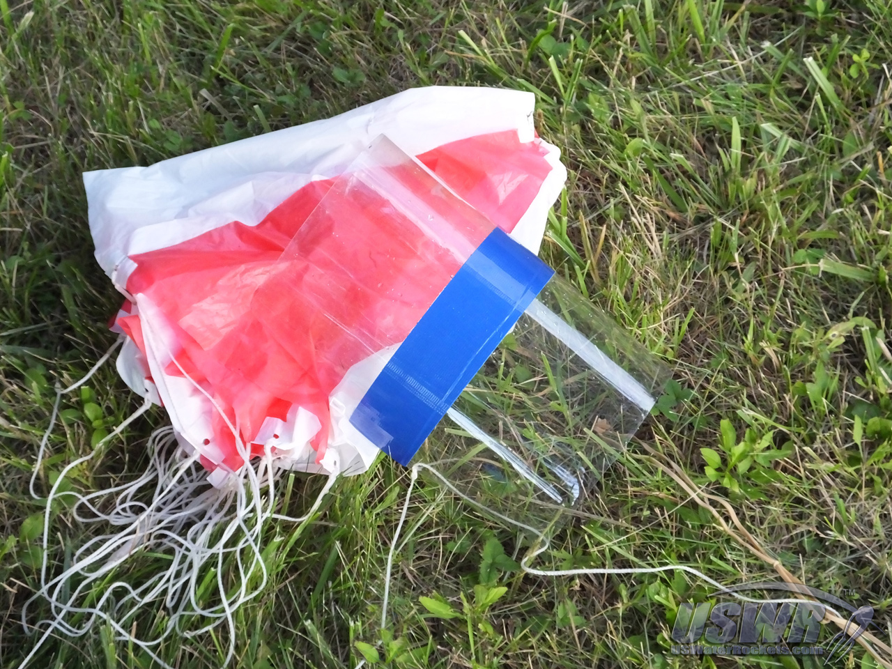
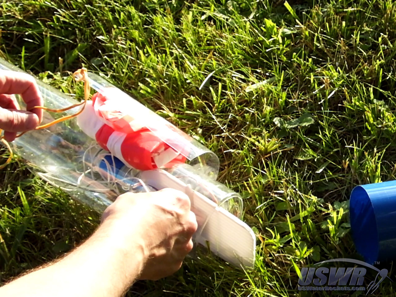
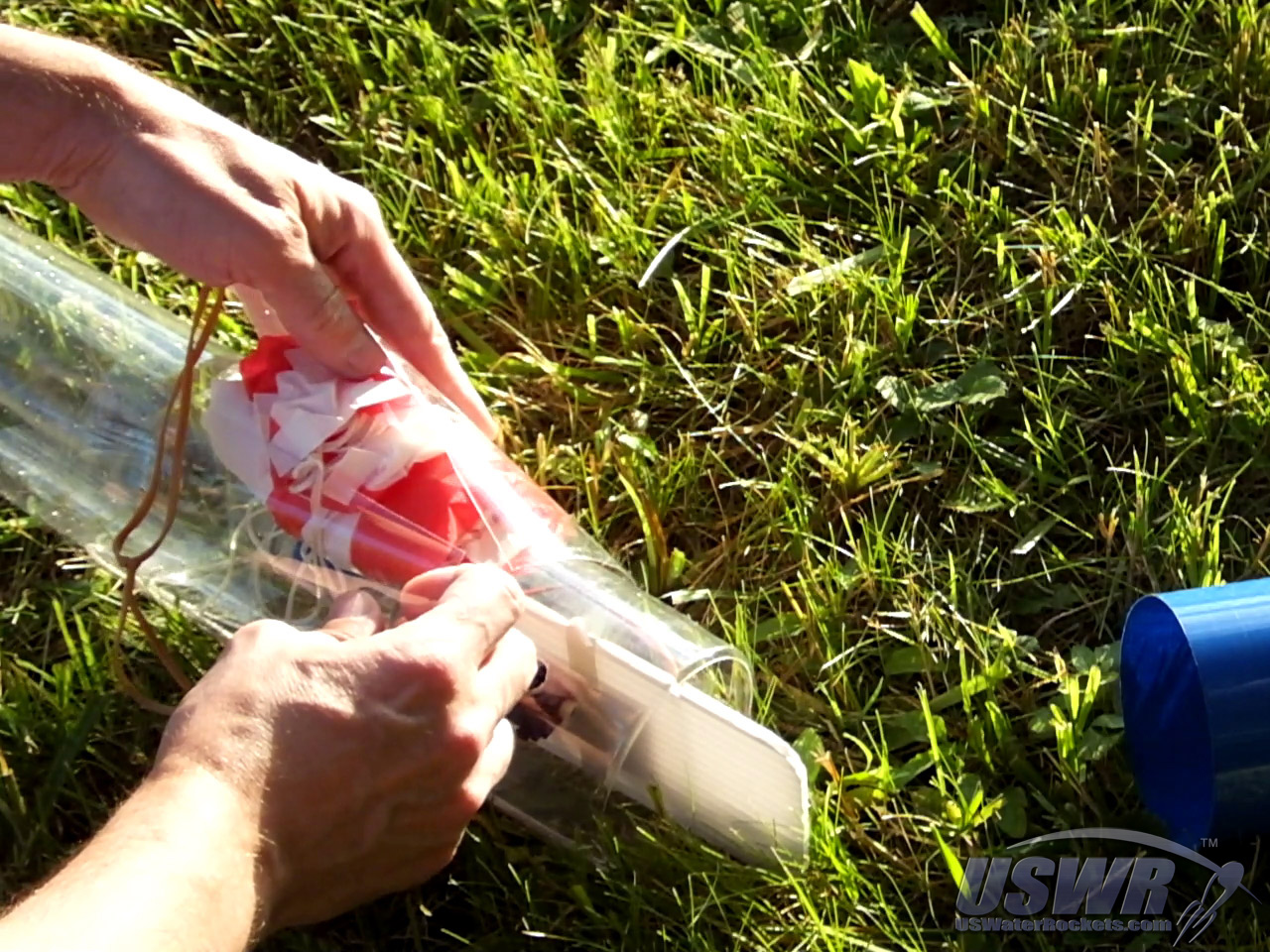
Step 2: Cover the parachute:
The excess parachute main shroud line is simply gathered in a loose bundle and pinned behind the parachute as we wrap the parachute cover around the bottles, filling the narrow spot between the bottle necks, and enclosing the parachute inside.Start wrapping the parachute cover with the edge that the main shroud line is connected to, and finish with the corner the rubber band is connected to on the outside of the overlap, with the rubber band corner at the bottom, farthest from the payload compartment.
Make sure that the parachute cover is overlapping the flat areas of the bottles above and below the parachute by about an inch (2.5cm) and that the parachute cover is not closer to the release mechanism or access holes than one half an inch (1.25 cm). This is to insure that if the bottles swell while being pressurized that they do not raise the parachute cover as they swell and block off any important access holes.
Gallery

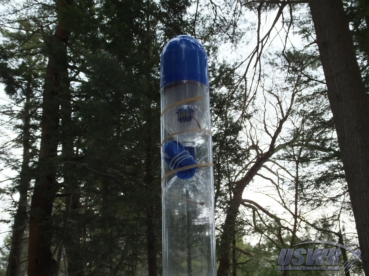
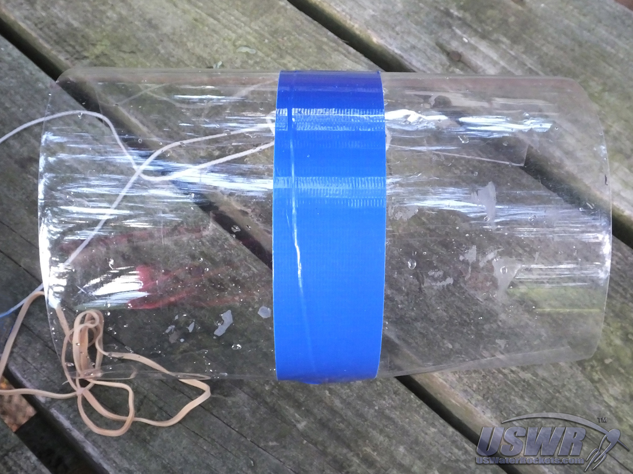
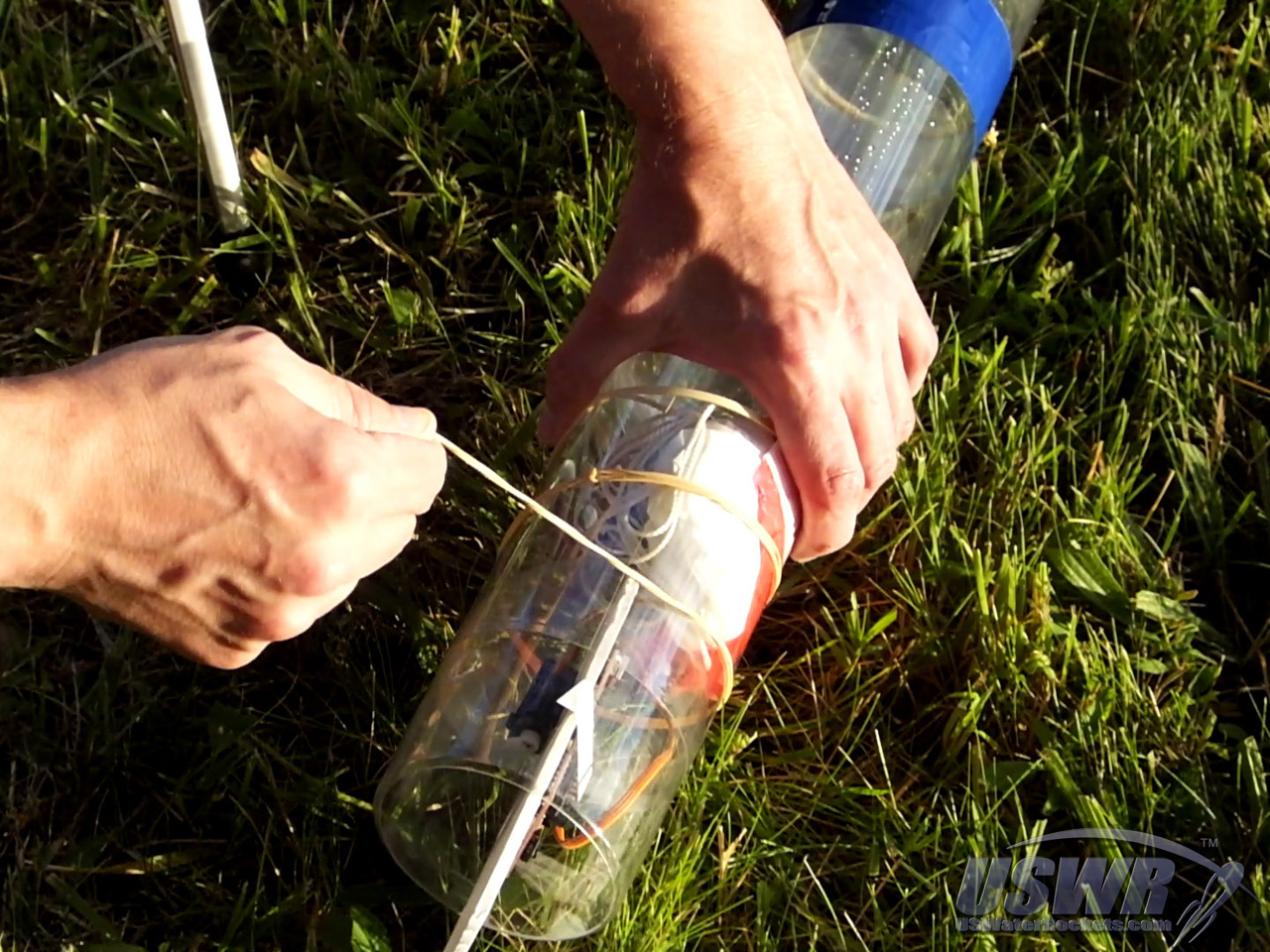
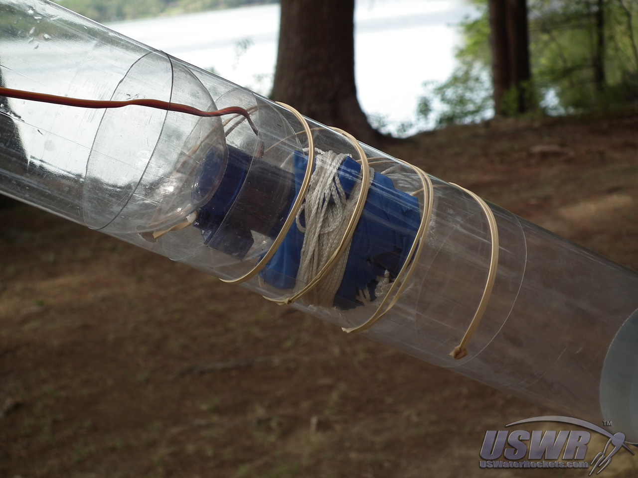
Step 3: Wrap the Rubber band:
Pull the rubber band very firmly to tightly constrict the parachute cover around the rocket.Take the rubber band and wind it in a spiral pattern around the parachute cover several times until it reaches the payload compartment, then hook the rubber band to the servo trigger mechanism.
The multiple windings of the rubber band constrict the parachute cover so tightly, it is almost impossible to move. If you need to adjust the alignment or position of the cover, you will have to release the tension on the rubber band.
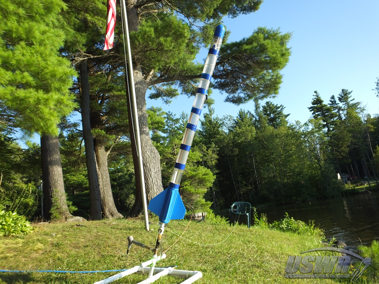
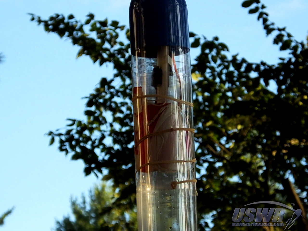
The radial deploy system is now armed and ready to launch.
Gallery


How the Radial Deploy parachute System Works:
The way in which the radial deploy system works deserves some explanation. The method is so simple, it relies on only one moving part: the rubber band, plus a little physics.When the deploy release is triggered, the rubber band is released, and it will begin to rapidly unwrap itself as it unwinds from the parachute cover. The tightly wrapped rubber band accelerates to a very high speed as it swings around the rocket, until it becomes fully unwrapped. At this moment, the rubber band is a swinging mass traveling at a very high speed, and the centripetal force easily pulls the parachute cover off the rocket. Since the parachute cover is connected to the main shroud line, it will pull the parachute away from the rocket as well.
Gallery
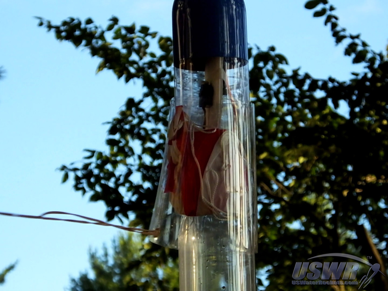
If the rubber band breaks off the parachute cover while it is unwinding, the parachute cover will still no longer be restrained and will usually slide or fall off, releasing the parachute.
If the parachute snags or sticks to the bottles for any reason, the open parachute cover will act as a drogue parachute and helps pull the parachute free.
[Back to Table of Contents]
Modifications:
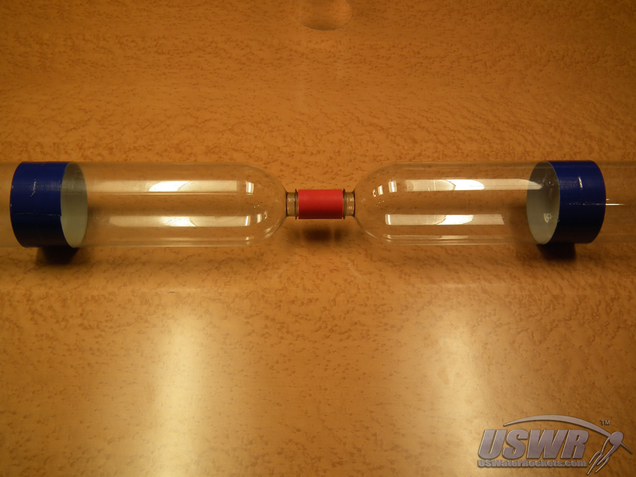
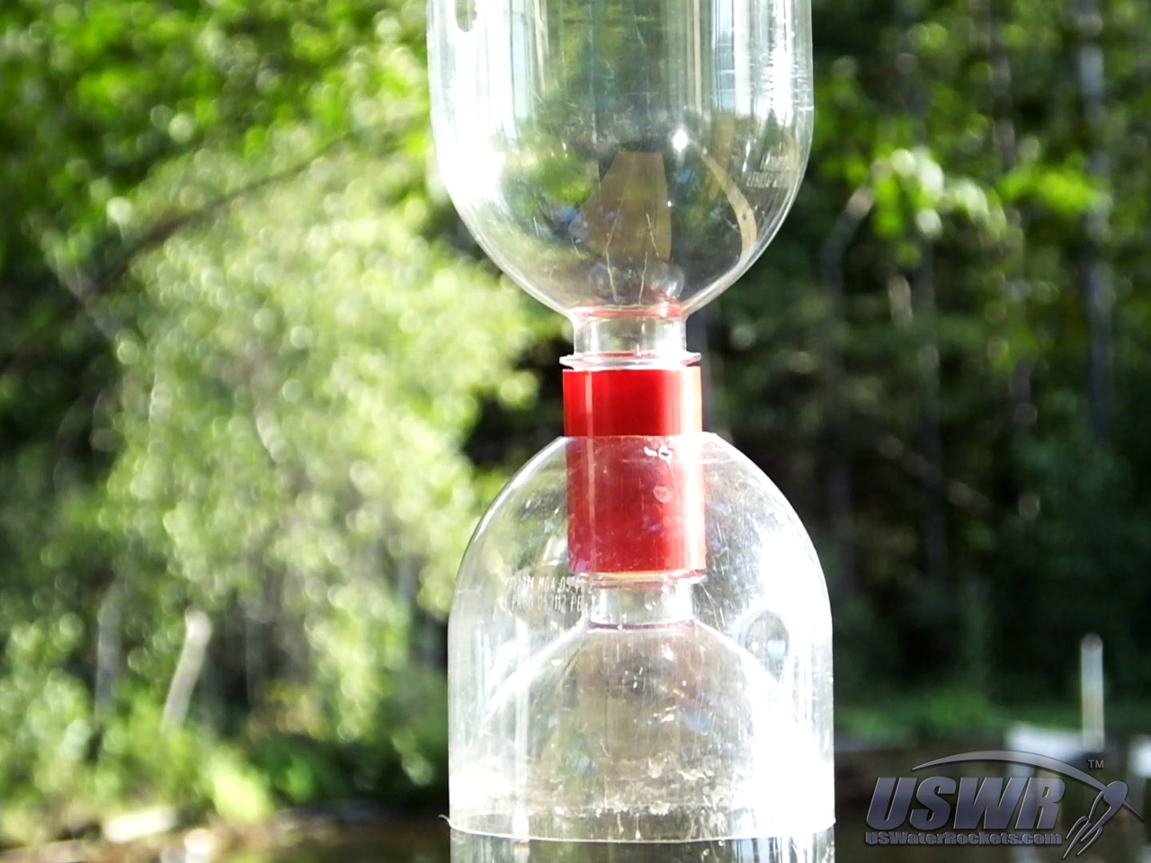
The radial deploy concept does not necessarily have to be located at the top of your rocket. It can also be placed in any position that has a tornado tube coupler or a narrow point. It could even be adapted to the narrow waist area of a coke bottle. This therefore allows you to mount the recovery system at any position along the length of the rocket, which can be useful for multiple parachute arrangements, or other experiments.To place the system at a tornado tube coupler position on your rocket, you will need to create a compartment for the parachute trigger. The method we have created for this purpose is to cut a short section of bottle beck and slide it over the tornado tube before threading on the upper bottle. The added neck portion forms a compartment inside which we mount our servo release. From that point on, the assembly is similar to the top mounted radial deploy system.
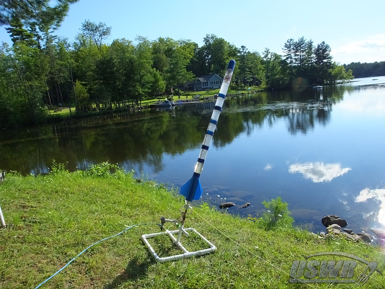
In this case, we mounted the radial deploy near the middle of our rocket, and one on the top so that we could have a small parachute deploy at apogee and a larger one deploy a few seconds later once the rocket had descended closer to the ground. The drogue chute was mounted in the central tornado tube area and the main chute was mounted at the top of the rocket. A long servo extension wire taped to the side of the fuselage was used to control the drogue parachute from the ServoChron™ located in the Payload Compartment.
Gallery
Final Thoughts:
We've shared this new deploy system with everyone, so that the design will help increase the reliability of water rocket launches, and inspire others to think outside the box to come up with new ideas and innovations. We hope you get many successful flights from this design.[Back to Table of Contents]
Radial Deploy Video Tutorial:
 Water Rocket Radial Parachute Deploy Mechanism by
U.S. Water Rockets is licensed under a Creative Commons Attribution-NonCommercial 3.0 Unported License.
Water Rocket Radial Parachute Deploy Mechanism by
U.S. Water Rockets is licensed under a Creative Commons Attribution-NonCommercial 3.0 Unported License.