


How to construct a Water Rocket Hybrid Parachute Deploy Mechanism.
Introduction:
The Hybrid Deploy System is our latest idea for improving water rocket systems to make them more reliable and easier to build. This system improves upon our previously published designs known as the Axial Deploy System, and Radial Deploy System. By combining the ease of construction of the Radial Deploy System, with the heavy duty capacity of the Axial Deploy System, we have created a new design that has the advantages of both, with none of the drawbacks. You may want to look at those systems in addition to this one to familiarize yourself with the designs.When compared to the types of deploy systems that people have been making for the past 10 or more years, the Hybrid Deploy System is improved in many ways:
- It is much easier to build.
- It takes far less time to build.
- It has a simpler operation that deploys more reliably.
- It is able to deploy a larger/heavier parachute.
- It can protect the payload if the parachute fails.
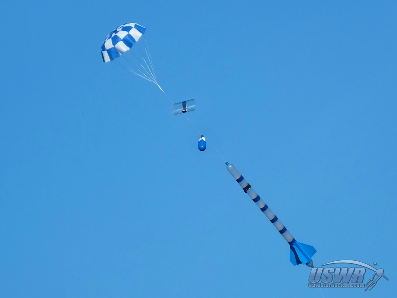

Table of Contents:
ConstructionArming the Deploy
How it works
Modifications
Video
Related Tutorials:
Building the Radial Deploy System:
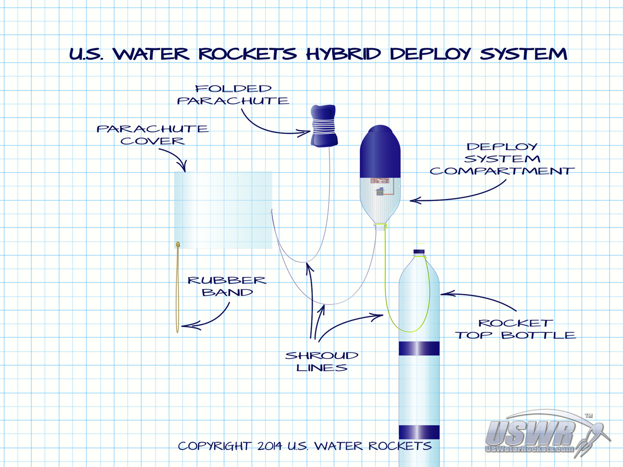
This tutorial explains how to make the Hybrid Deploy System, and how it works. For simplicity we will show a typical configuration for this design. There are several variations to the design which will be discussed at appropritate points in the discussion of the individual tutorial steps. Consult the diagram at the top of this tutorial to see the location of the various components as you construct your own Hybrid Deploy System.Gallery


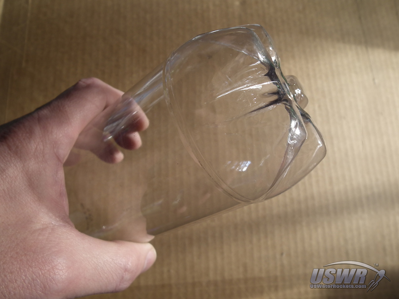
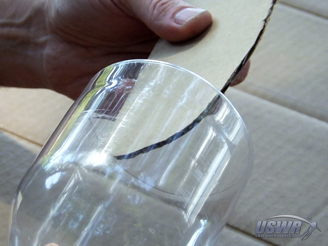
Step 1: Make the payload compartment for the deploy trigger mechanism.
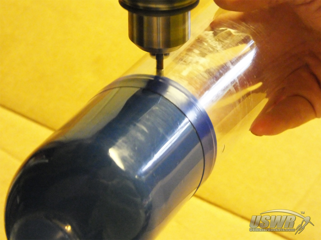
The payload compartment will contain the release mechanism that triggers the parachute system, and will typically be connected to the top of the rocket. The payload compartment is made by cutting a bottle in half and then turning it over so the neck is at the bottom.The cut edge of the payload compartment can optionally be curled inward to give it some strength and makes sliding the nosecone off the top easier.
Gallery


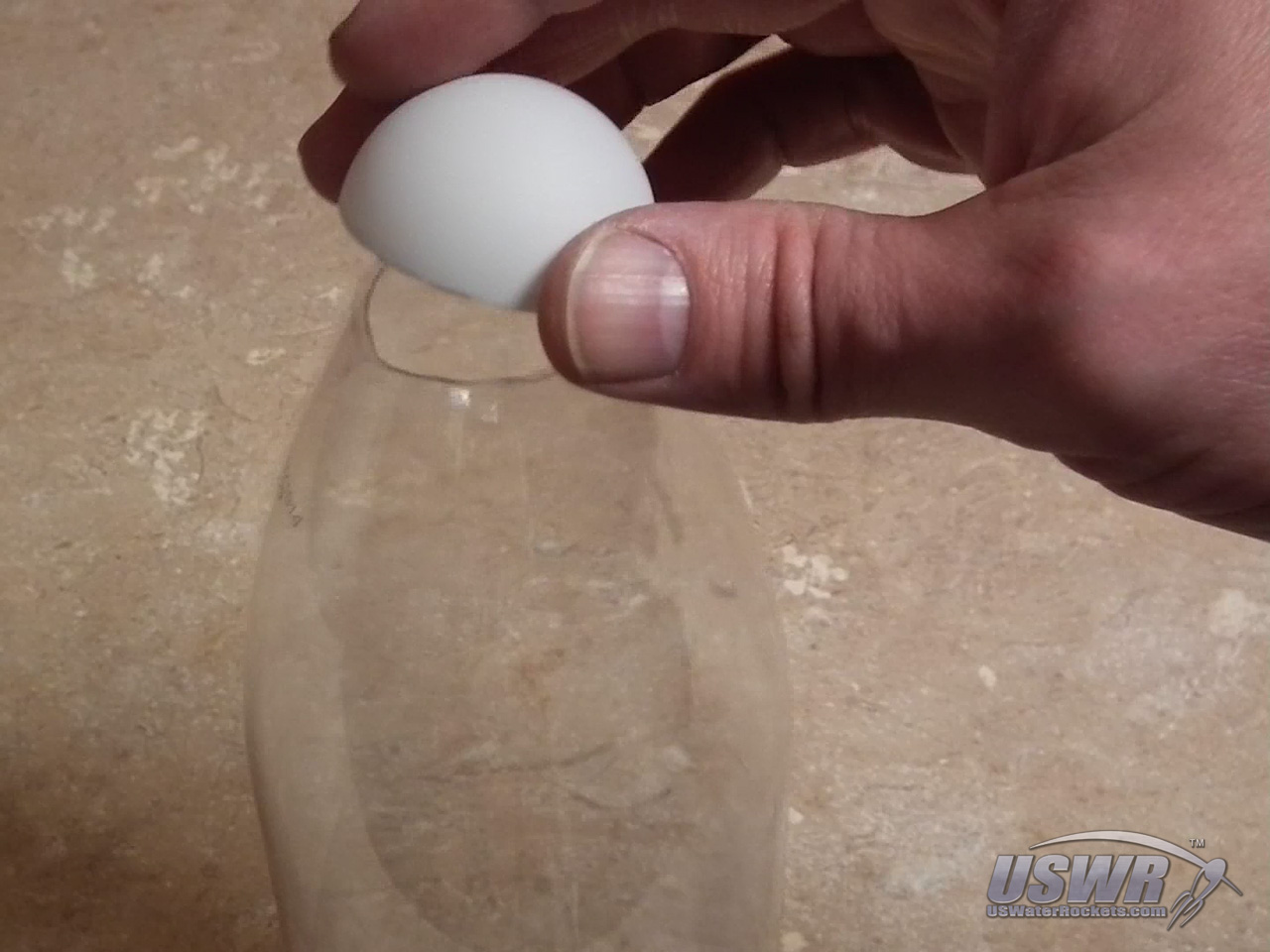
Step 2: Make a nosecone for the open end of the payload compartment.
To make a nosecone, you will need to cut the top half off a second bottle and slide it over the open end of the payload compartment. For improved aerodynamics, you can cut the neck off the top of the nosecone and cover the hole with a plug cut from a plastic egg, or table tennis ball. ...Gallery
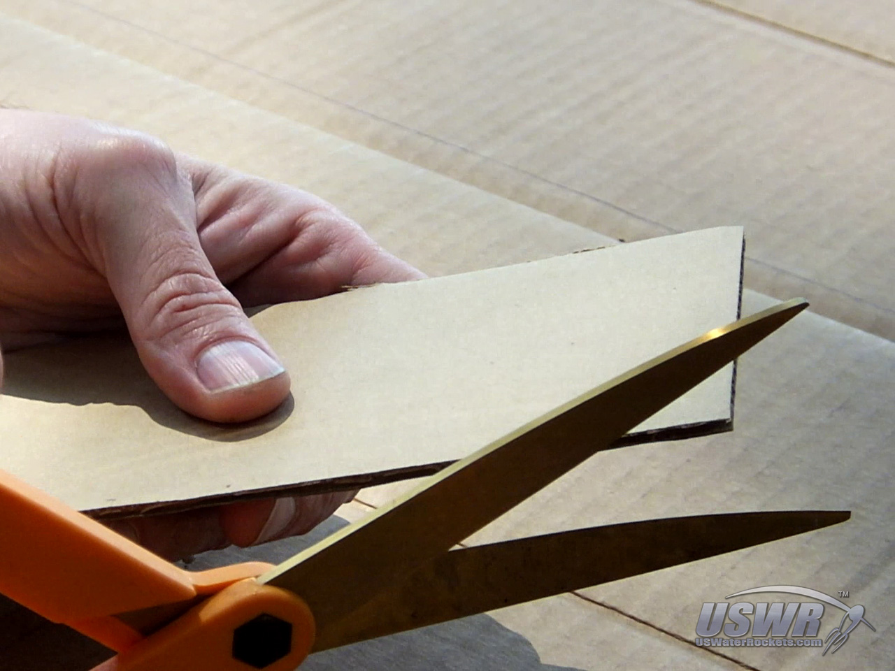
Step 3: Make a support bulkhead for your trigger mechanism.
A place to mount the trigger mechanism inside the payload compartment is made next. You can cut it from a piece of balsa wood, cardboard, or corriflute. The purpose of the support bulkhead is to provide a structure to mount the release mechanism to. Your design will depend on the shape of you payload compartment and the trigger you use. You can optionally attach the release mechanism to the wall of the payload compartment, and skip this step.Gallery
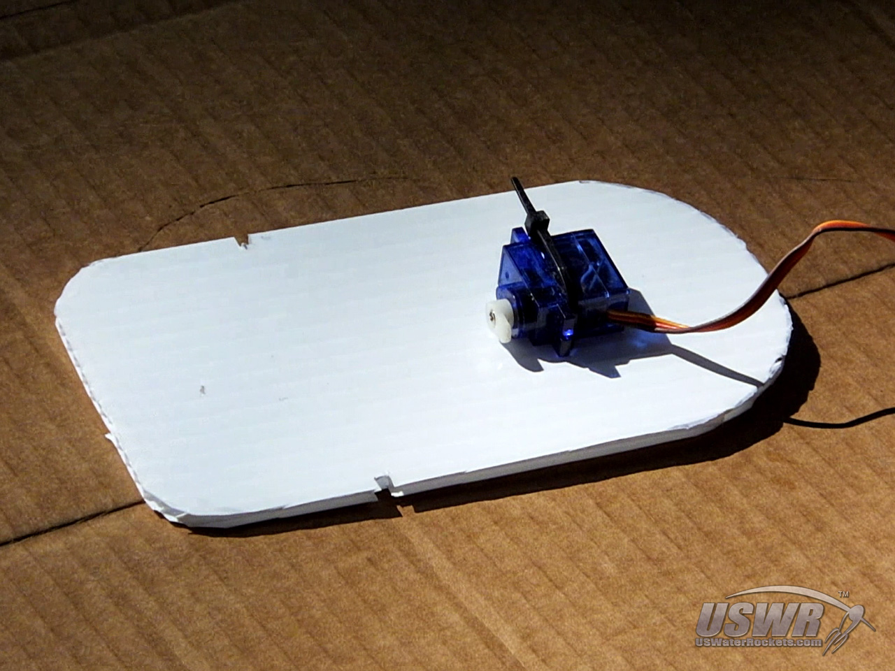
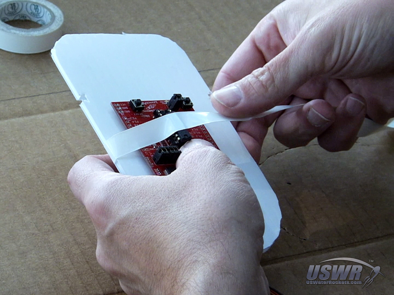
Step 4: Mount the Deploy Trigger Mechanism to the Support Bulkhead.
In this design, we show how we mount our deploy trigger in place using cable ties, and electrical tape. You can mount your system as we have, or in any other way that is convenient for you. You will need to adapt this step for whatever mechanism you use.Gallery
LaunchPad AlTImeter Manual
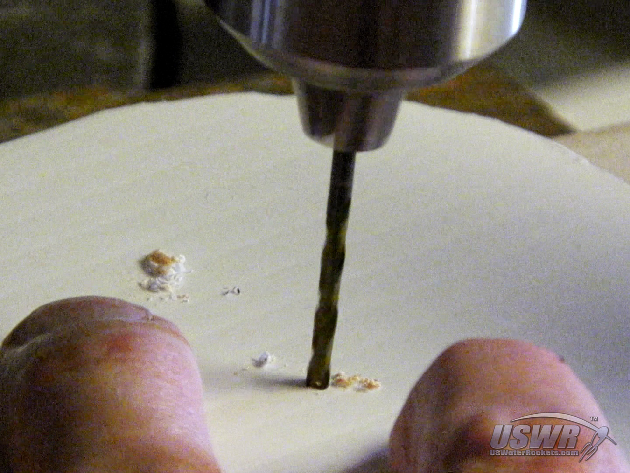
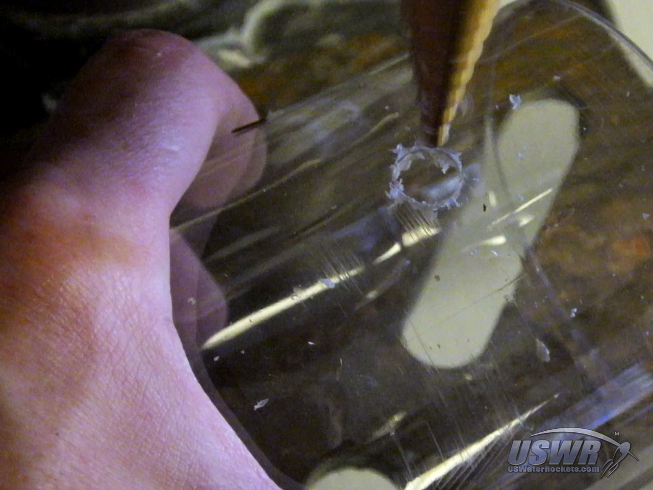
Step 5: Make any necessary access holes in the payload compartment.
Different types of trigger mechanisms require different holes in the payload compartment to give access to the mechanism and to attach a rubber band that will be used later to arm the system. If your trigger mechanism needs to be armed or powered on in some manner, you can now make any necessary holes in the payload compartment that will provide access from outside so it can be manipulated. This is the best time to make these holes, since the support bulkhead is now in place and it is very easy to locate where you need to place any access holes and cut or drill them. You can now assemble the payload compartment to the rocket and put the nosecone on.Gallery
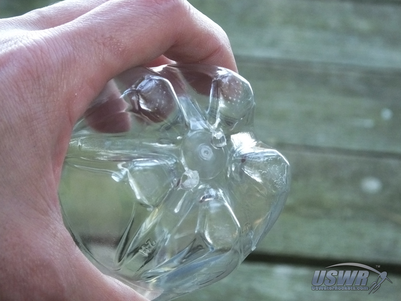
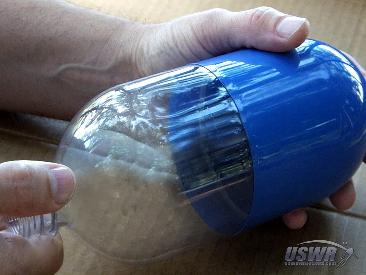
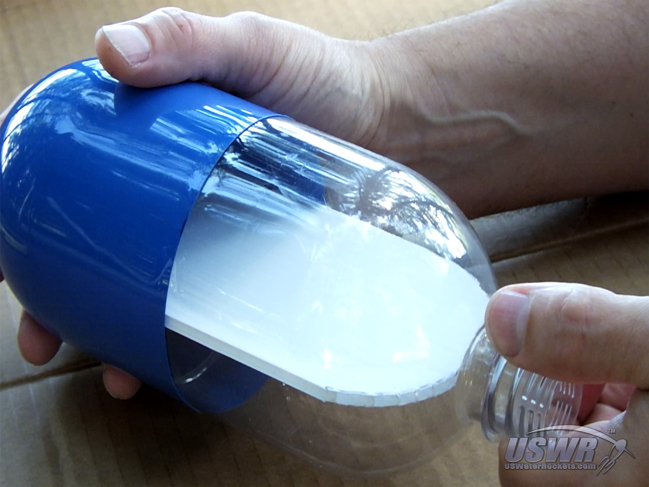
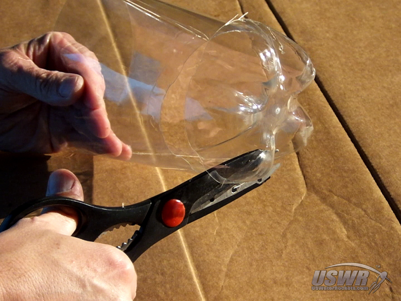
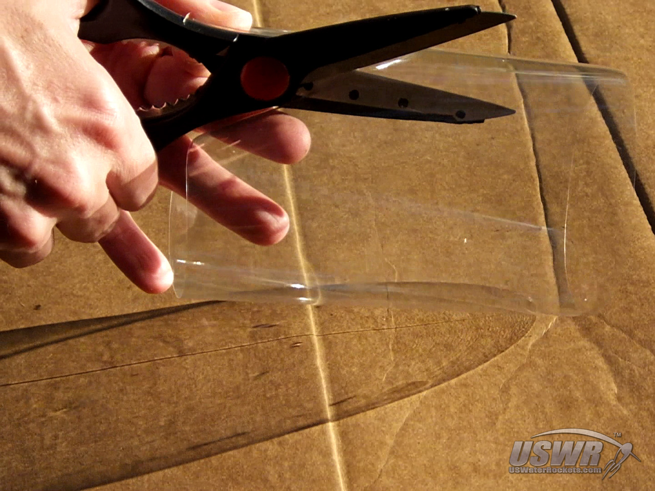
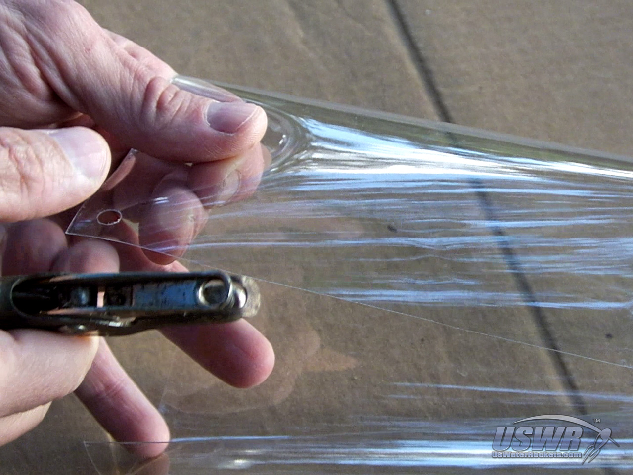
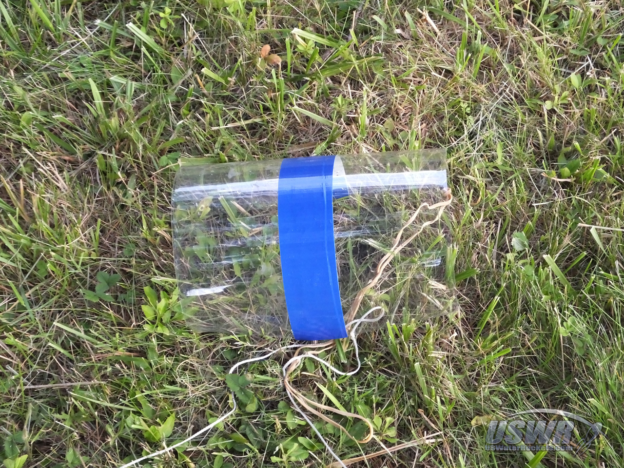
Step 6: Make the parachute cover.
The parachute cover is a flat sheet of plastic. This can be made from a bottle with the neck and base cut off, leaving a cylindrical sheet of plastic that is then sliced vertically and flattened out.The parachute cover must be wide enough to wrap around the rocket and overlap itself about 1 inch (2.5cm), and it must be tall enough to span the gap between the top of the rocket and be bottom of the payload compartment with about 1 inch (2.5cm) of contact area on the top and bottom edges. If you do not have enough contact area, the parachute cover becomes very tricky to install.
Gallery
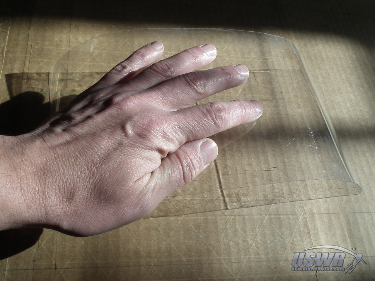
If you make the parachute cover from a bottle, it is best made from a bottle that is larger in diameter than the bottles you made your rocket from.
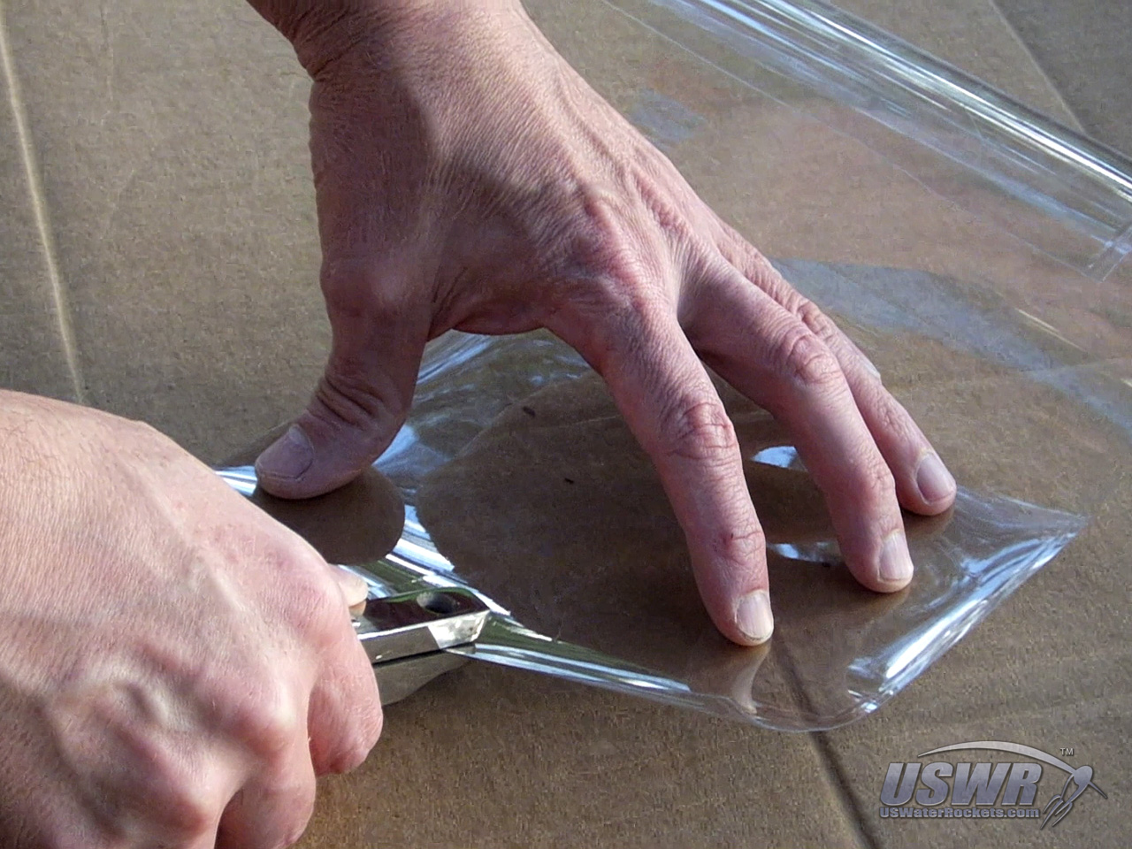
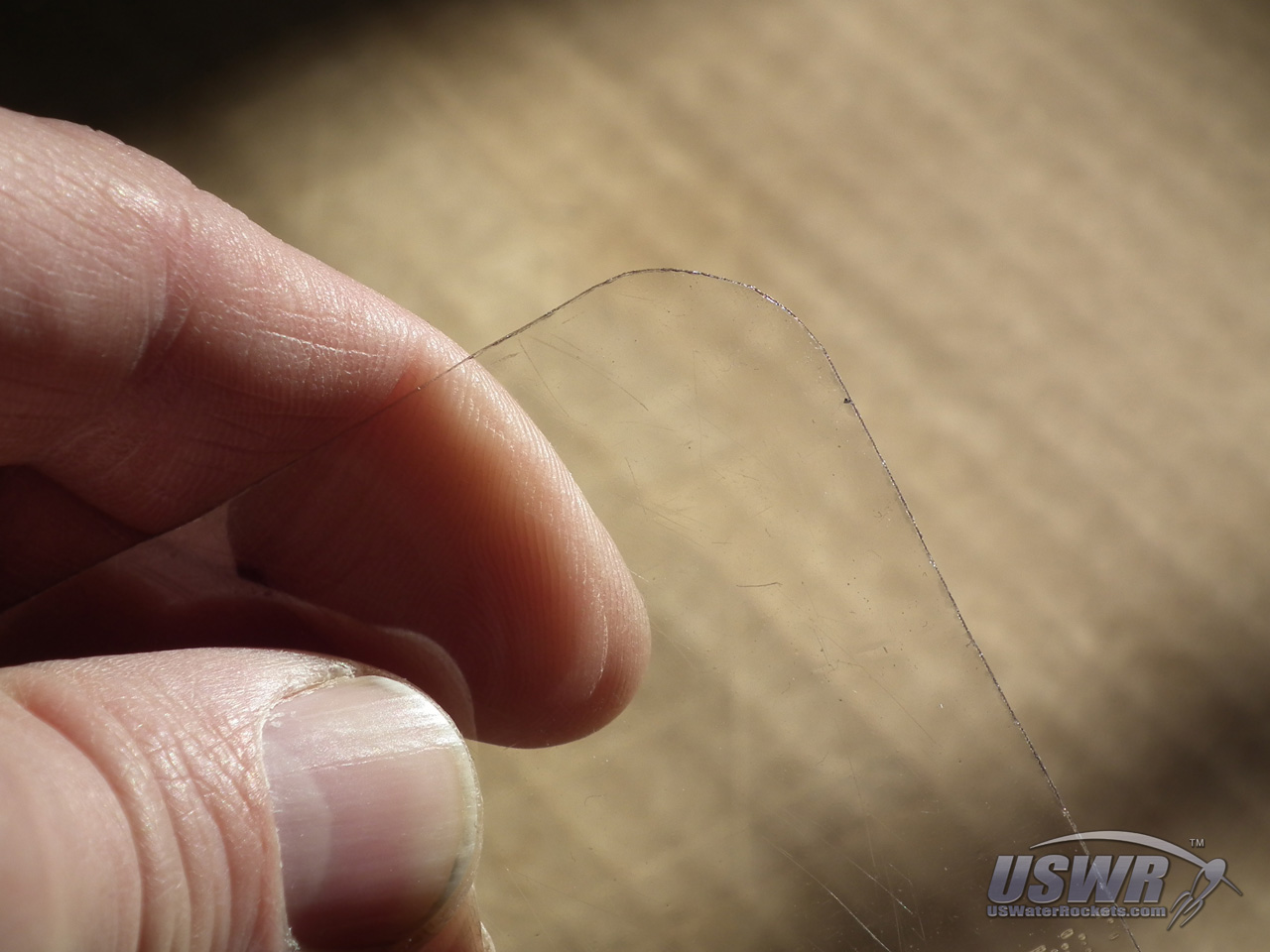
Step 7: Make holes to attach the Parachute Cover to the Rocket.
Two holes must be made in the parachute cover. One hole is located in one of the corners of the cover, and the other is in the middle of the opposite vertical edge of the cover. These holes will be used as tie points. You can optionally cut the sharp corners off the parachute cover to make them slightly rounded. We have found that this helps make a smoother deploy operation.Gallery
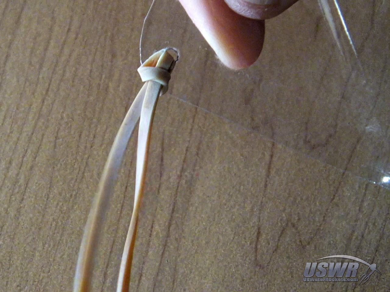
Step 8: Attaching to the parachute cover.
Tie the main line of the parachute to the parachute cover about 1/3 of the way between the parachute itelself, and the end of the main line.A long rubber band is connected to the hole in the corner of the parachute cover. The length of this rubber band will vary depending on the diameter of the rocket size, but you can easily add additional rubber bands by linking them together to adjust the length as necessary.
Gallery

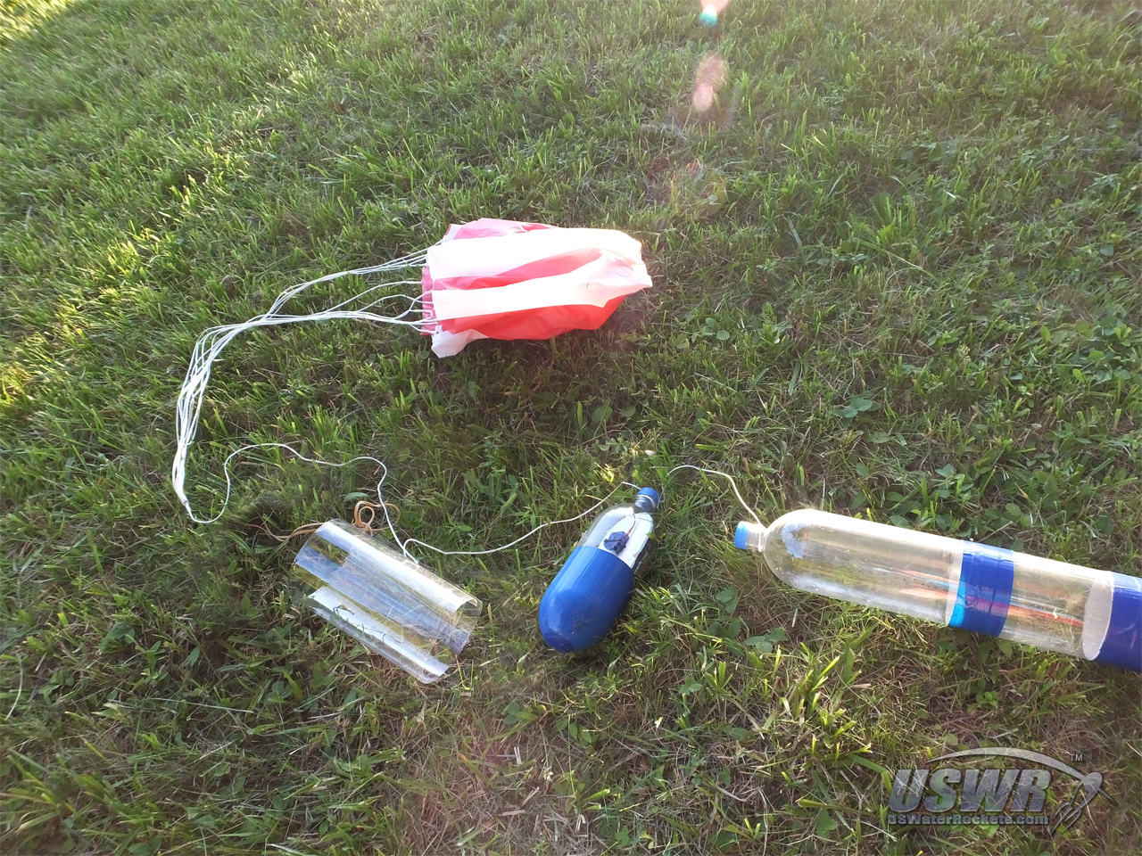
Step 9: Connect the Parachute to the Rocket.
Take the main line of the parachute, and tie it to the payload compartment about 1/3 of the length of the main line from the loose end. Then take the loose end and tie it directly to the top of the rocket.Gallery


Arming the Hybrid Deploy System:
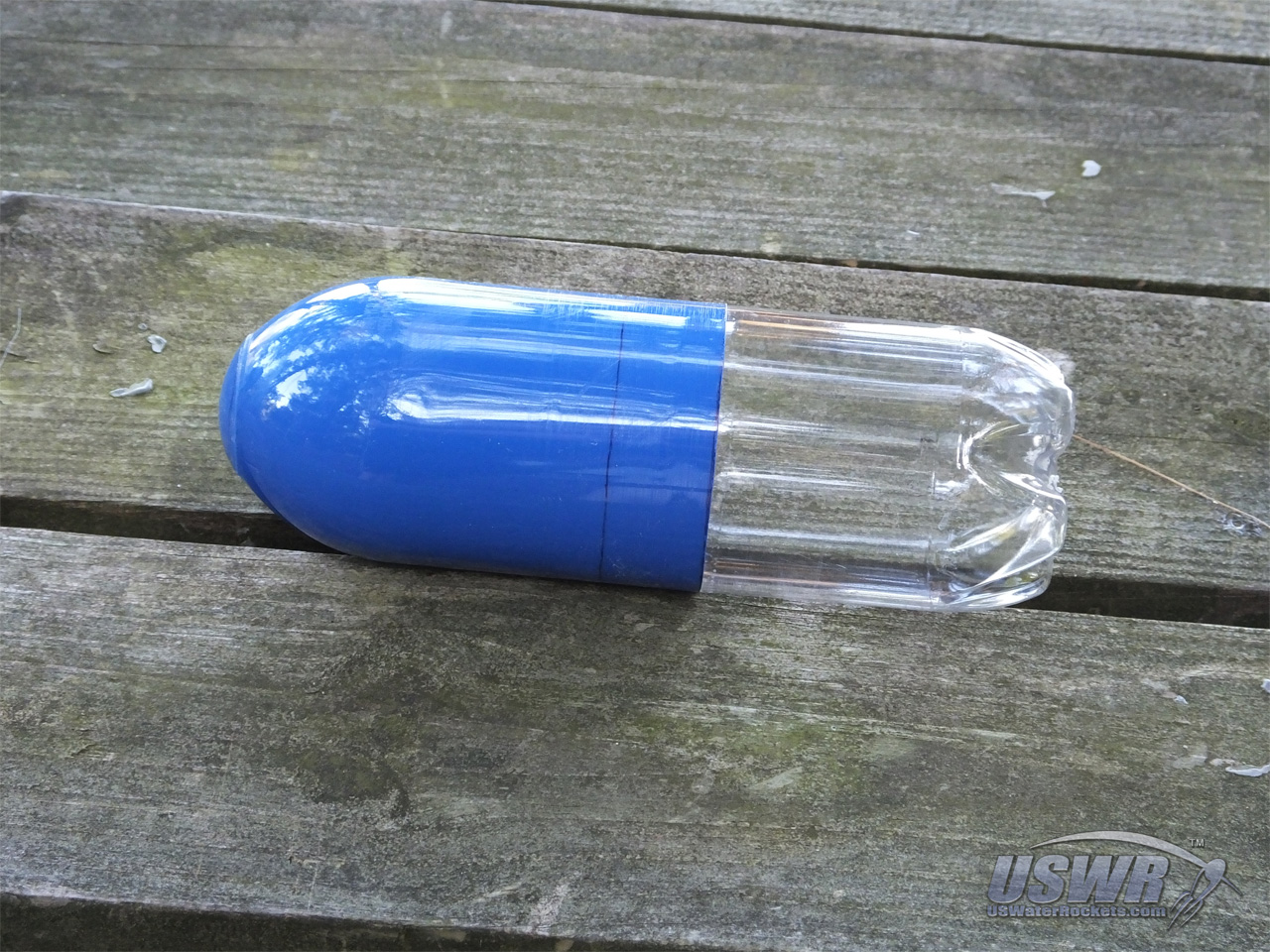
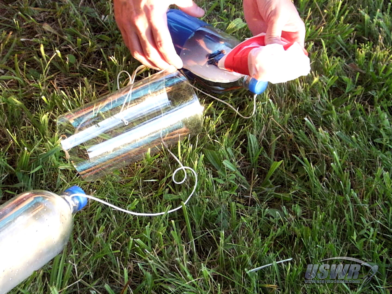
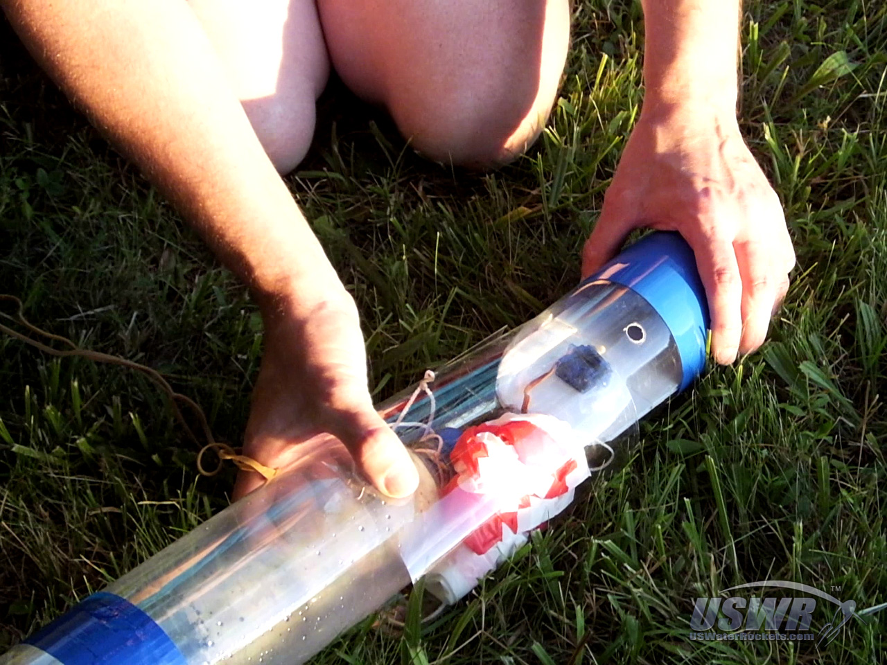
A few steps are needed to arm the Hybrid Deploy System to insure a successful parachute recovery. Follow the directions below to insure that you have the best possible results.Step 1: Stowing the Parachute.
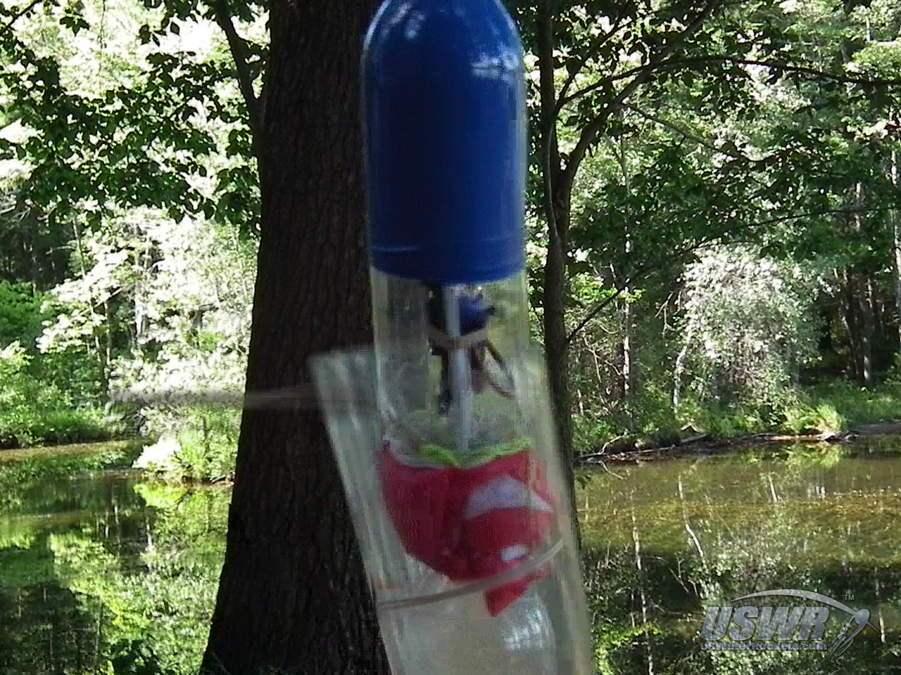
Take the parachute and fold it however you prefer, bearing in mind that it will function better if you fold it loosely and avoid compressing it into a tight wad. Once folded, you can stow the parachute next to the neck at the top of your rocket.The Parachute cover is wrapped around the tip of the rocket, and held from falling off with your hand. Make sure that the edge of the cover with the rubber band is on the edge farthest away from the parload compartment and is on the outside layer when the cover is wrapped around. The cover will hold the parachute in place while the parload compartment is slid into the open end of the parachute cover on top. As you insert the payload compartment, the excess parachute line can be tucked in next to the parachute.
Gallery
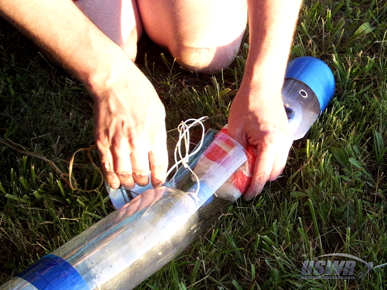
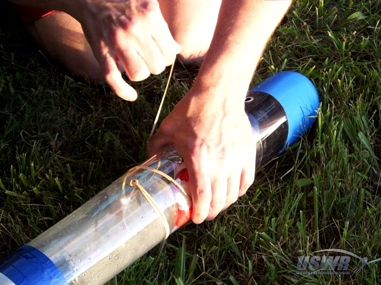
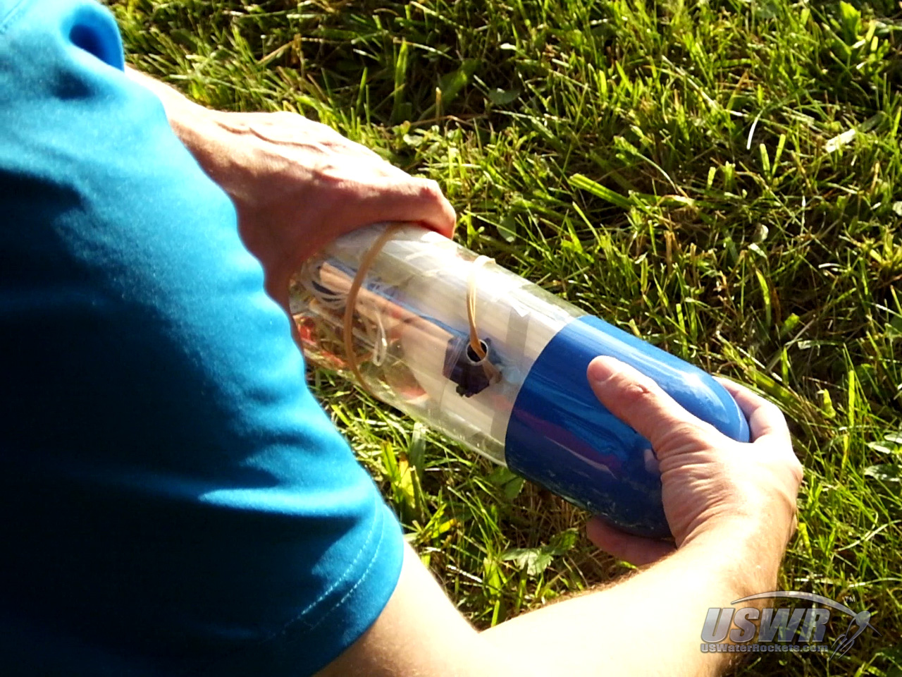
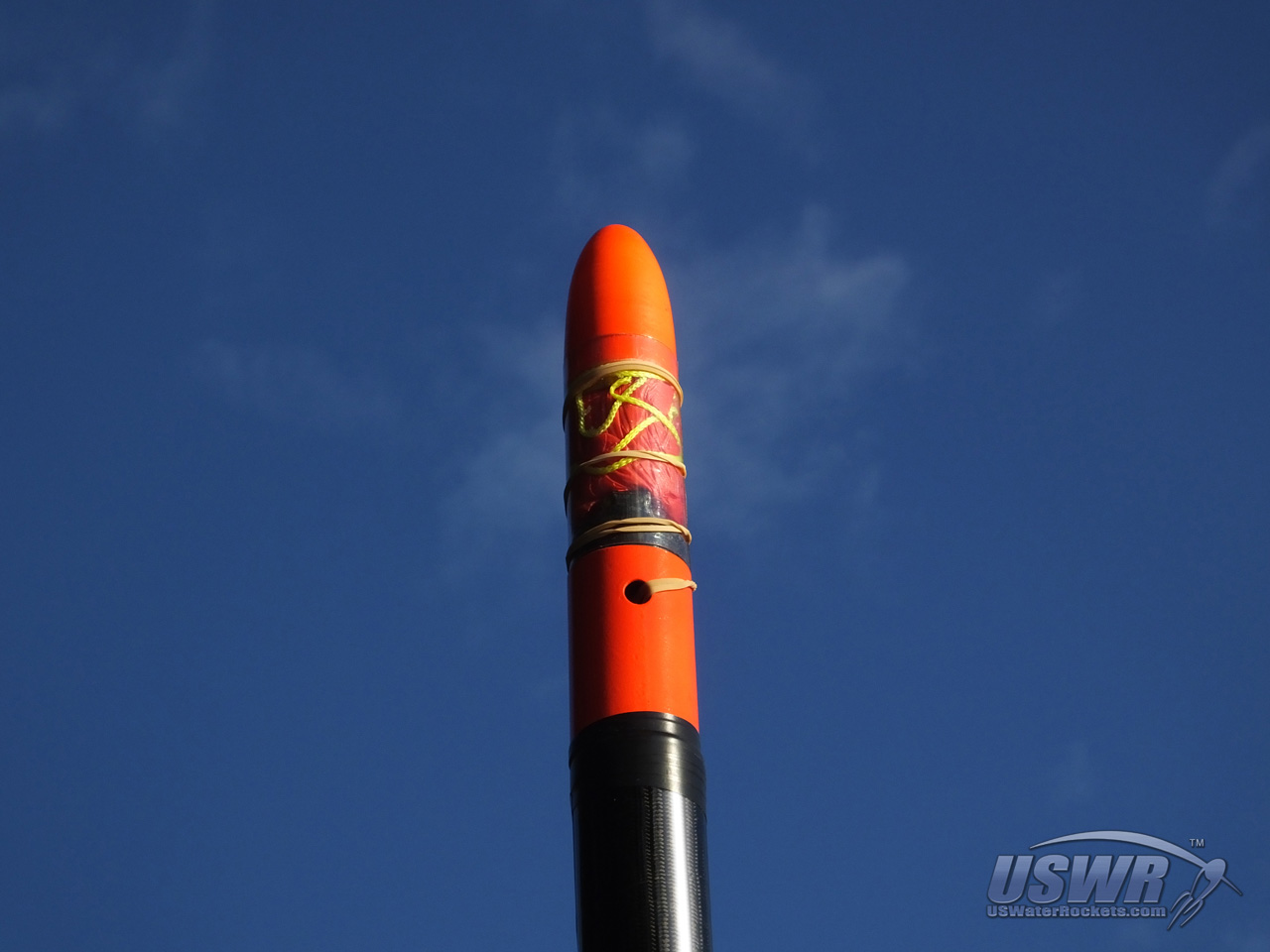
Step 2: Secure the Parachute Cover:
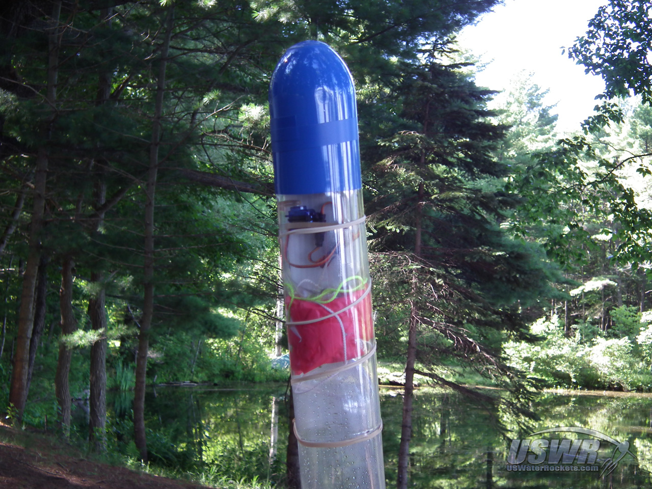
Pull the rubber band very firmly to tightly constrict the parachute cover around the top of the rocket.Take the rubber band and wind it in a spiral pattern around the parachute cover several times until it reaches the payload compartment, then hook the rubber band to the trigger mechanism. Make sure that the parachute cover is overlapping the rocket evenly on top and bottom and is not covering any holes needed to operate the deploy system.
The multiple windings of the rubber band constrict the parachute cover so tightly, it is almost impossible to move. It holds the payload compartment very tightly to the top of the
rocket. If you need to adjust the alignment or position of the cover, you will have to release the tension on the rubber band.
Gallery
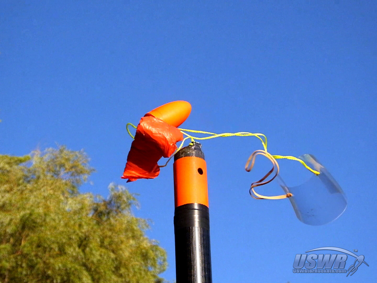
How the Hybrid Deploy parachute System Works:
The way in which the Hybrid Deploy System works requires some explanation.When the deploy release is triggered, the rubber band is released, and it will begin to rapidly unwrap itself as it unwinds from the parachute cover. The tightly wrapped rubber band accelerates to a very high speed as it swings around the rocket, until it becomes fully unwrapped. At this moment, the rubber band is a swinging mass traveling at a very high speed, and the centripetal force pulls the parachute cover off the rocket. At the same time, the tension on the parachute cover that is holding it to the rocket and payload compartment at each end will go away, and the two will separate from each other and fall away. Since the parachute cover and payload compartment are both connected to the main shroud line, they will pull the parachute away from the rocket as they fall away. The large mass of the payload compartment in addition to the drag on both it and the parachute cover, will insure that a huge force is being applied to pull the parachute free.
Gallery


The design of this system eliminates unnecessary moving parts, and places where the parachute can tangle or snag, which increases the reliability dramatically. Additionally, the design provides multiple redundancies which can still cause a successful deploy in the rare event of a failure.
If the rubber band breaks off the parachute cover while it is unwinding, the parachute cover will still no longer be restrained and the payload compartment will simply fall off, deploying the parachute with it.
The large mass of the payload compartment connected to the parachute line will insure that even a stubborn or stuck parachute will have the best chance to be pulled free.
Additionally, in the event that the parachute tears, or somehow fails to inflate, a hidden benefit of the Hybrid Deploy System is that it offers a bit of extra protection to the payload when this happens. This is because the payload compartment is no longer attached to the nose of the falling rocket, and will not have to survive the crushing force of the rocket coming down on it when it impacts the ground. Any valuable cameras, altimeters, or other payloads will be much more likely to survive the crash if they are not subjected to the crushing force between the ground and the rest of the rocket.
[Back to Table of Contents]
Modifications:
The position of the parachute cover and the payload compartment on the parachute line can be modified to suit your needs. They do not have to be tied to the line at any specific distance from the ends or from each other. We have test launched with the distances at various lengths and even swapped their positions on the line and it did not seem to affect the reliability of the system. Feel free to experiment and see what works best for your rockets.The hybrid deploy system does not require that the entire payload compartment be positioned above the parachute. The electronics or deploy trigger timer could just as easily be contained in the space below the parachute and only the nosecone needs to be placed on top. This arrangement will lose the crash protection aspect for the payload compartment, but may appeal to you because it more closely resembles an Axial type of deploy. We used this configuration on our X-10 rocket for test flights, because we had an existing recovery system on the rocket already which could be changed over to this mode without any modifications to the rocket or payload compartment.
Gallery

Final Thoughts:
We've shared this new deploy system with everyone, so that the design will help increase the reliability of water rocket launches, and inspire others to think outside the box to come up with new ideas and innovations. We hope you get many successful flights from this design.[Back to Table of Contents]
Hybrid Deploy Video Tutorial:
 Water Rocket Hybrid Parachute Deploy Mechanism by
U.S. Water Rockets is licensed under a Creative Commons Attribution-NonCommercial 3.0 Unported License.
Water Rocket Hybrid Parachute Deploy Mechanism by
U.S. Water Rockets is licensed under a Creative Commons Attribution-NonCommercial 3.0 Unported License.