


3D Printed Star Wars Droid Replica
Introduction:
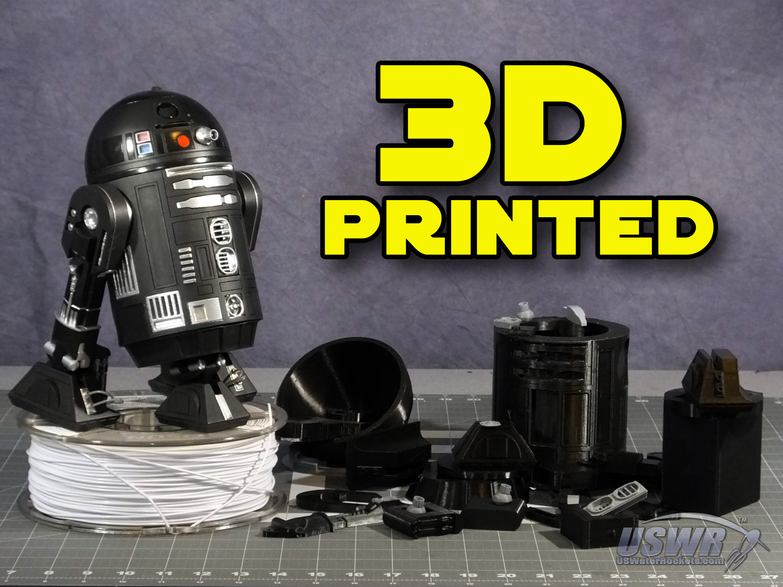
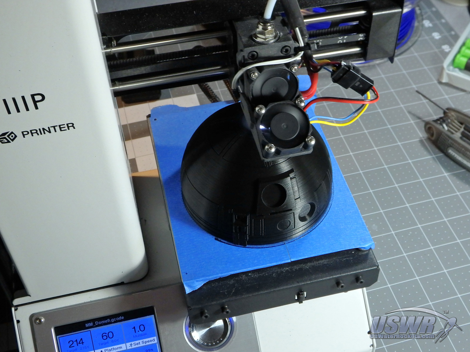
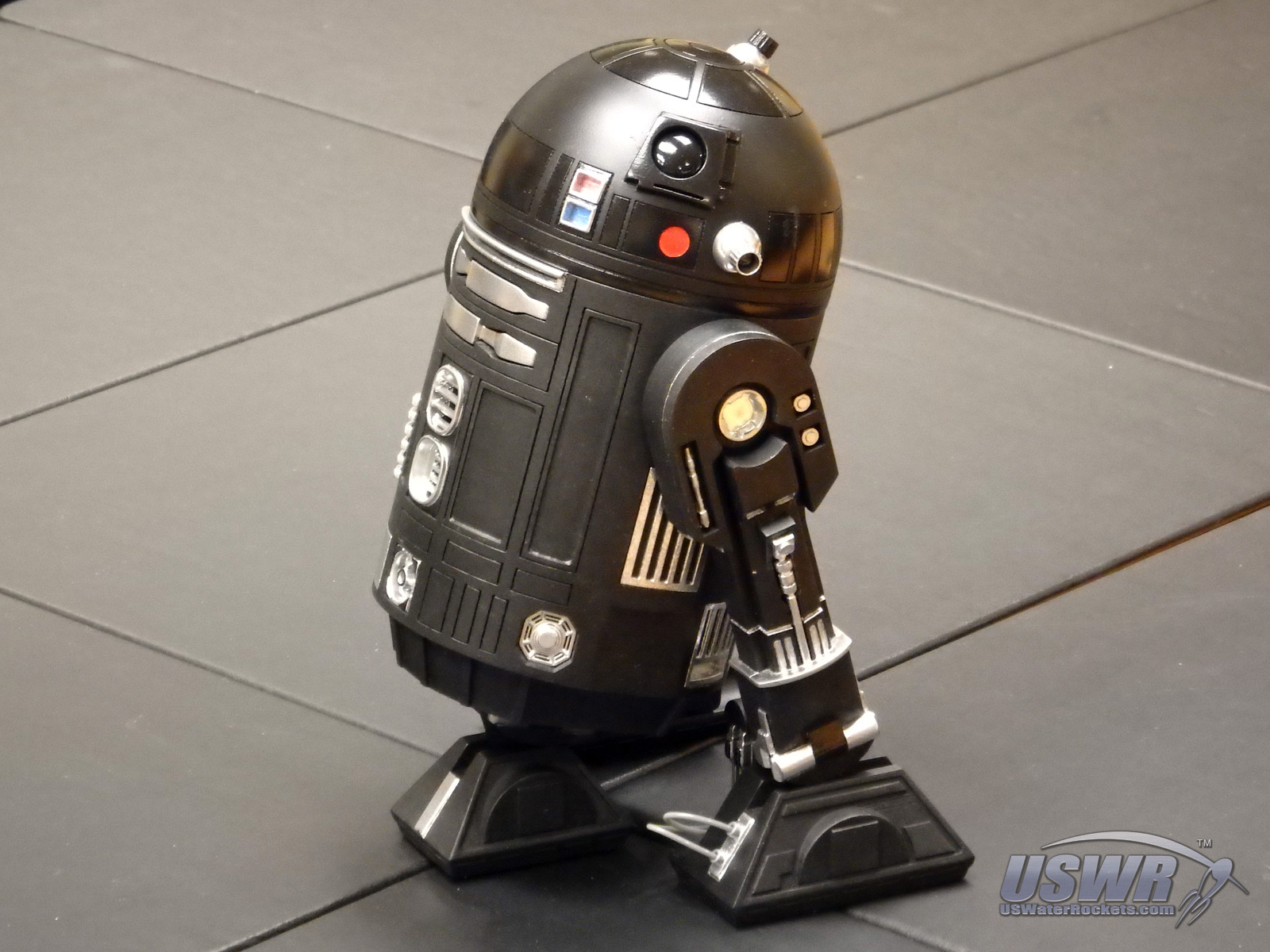
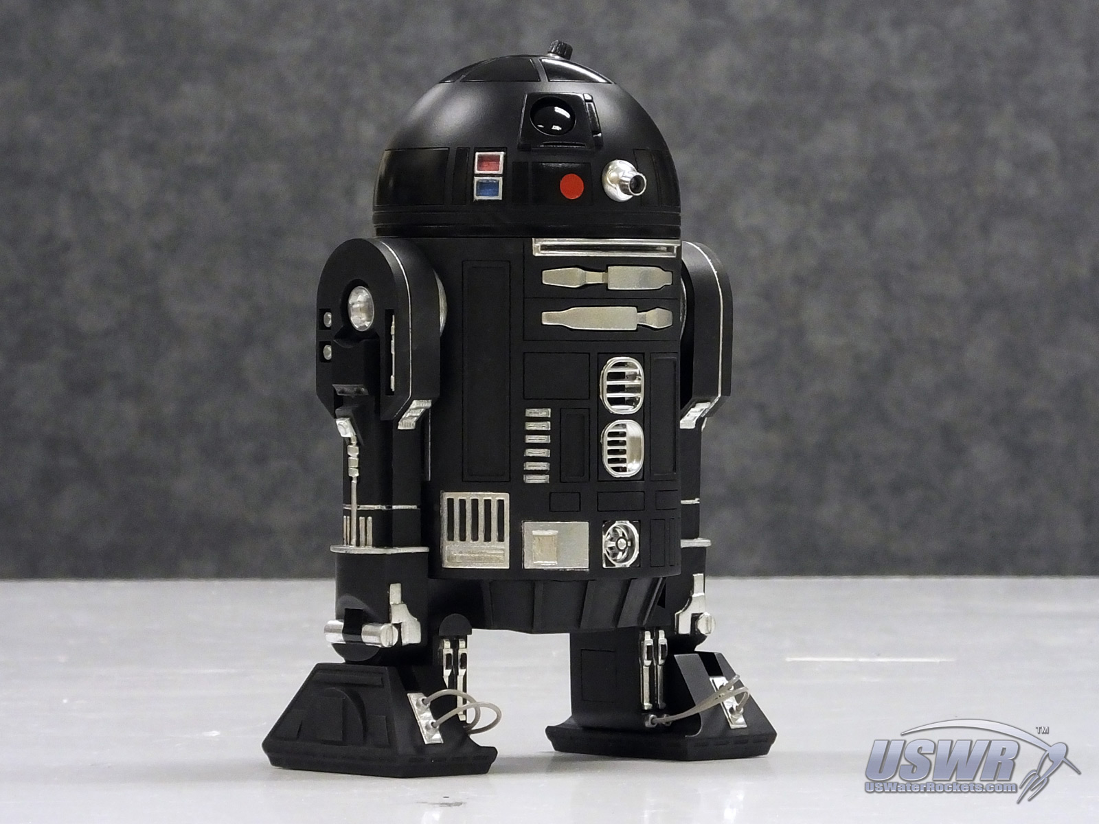
U.S. Water Rockets is proud to release this nearly ¼ Scale accurate droid replica for 3D printing. This replica robot from the Star Wars Universe was designed to be the most detailed and accurate 3D Printable Astromech droid you can print, with exceptional detail lacking in other printable models. This project was inspired by some of the replica prop builds done by Adam Savage, featured on Tested.com and YouTube. The design was created completely from scratch, using reference stills from the movies and drawings available online produced by the R2 Builders Club (astromech.net). The design and build took place over the course of several months as a learning project to explore the limits of FDM 3D printing, and learn how to break down a complex design in order to print it with greater fidelity. A side benefit of this process is that it enables a much larger print to come from a small 3D printer.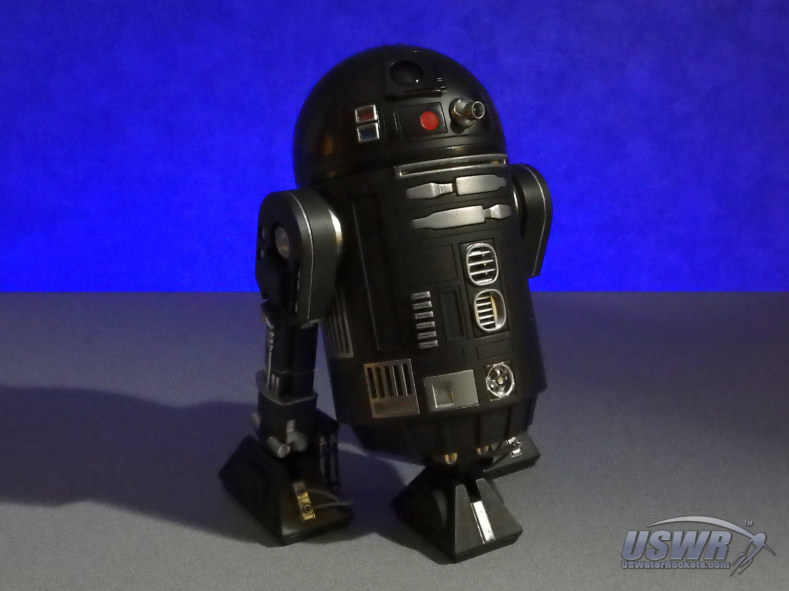


Gallery

| Part | Quantity | Printing Notes | |
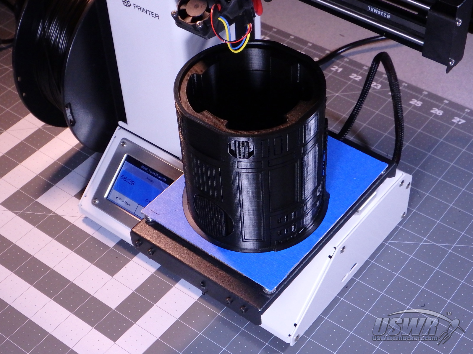
| Torso | 1 | Some Support is recommended | |
| Dome | 1 | ||
| Skirt | 1 | ||
| Neck_Ring | 1 | ||
| Center_Retract_Track | 1 | ||
| Center_Retract_Top | 1 | ||
| Center_Retract_Slider | 1 | ||
| Center_Foot | 1 | ||
| Center_Leg_Half | 2 | ||
| Leg_Outer | 2 | Rotate 45 degrees to fit small beds | |
| Shoulder_Hub | 2 | ||
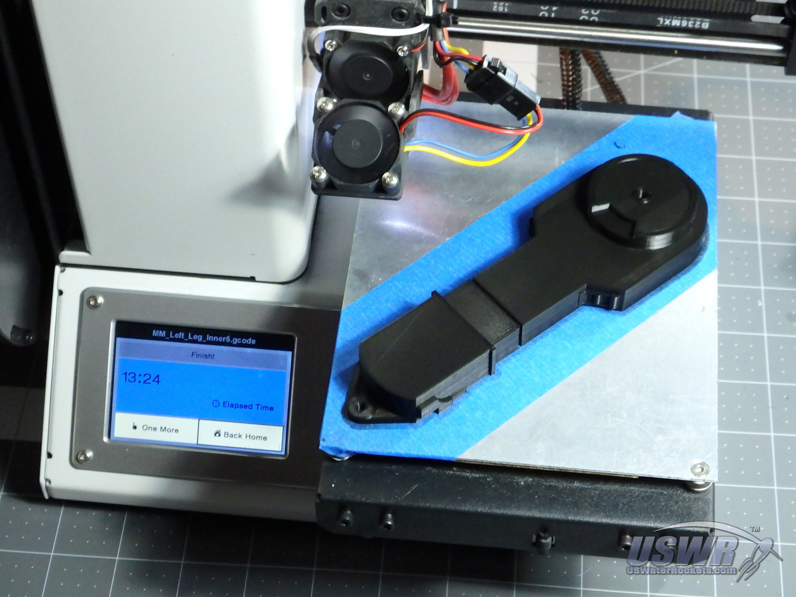
| Left_ Leg_ Inner | 1 | Rotate 45 degrees to fit small beds | |
| Left _Shoulder | 1 | ||
| Left _Foot | 1 | ||
| Left_Battery_Box | 1 | ||
| Left_Battery_Door | 1 | ||
| Right_ Leg_ Inner | 1 | Rotate 45 degrees to fit small beds | |
| Right_Shoulder | 1 | ||
| Right_Foot | 1 | ||
| Right_Battery_Box | 1 | ||
| Right_Battery_Door | 1 | ||
| HoloProjector | 3 | ||
| Center_Vent | 1 | ||
| Octagon_Port | 2 | ||
| Power_Coupling | 2 | ||
| Radar_Eye | 1 | ||
| Utility_Arm | 2 | ||
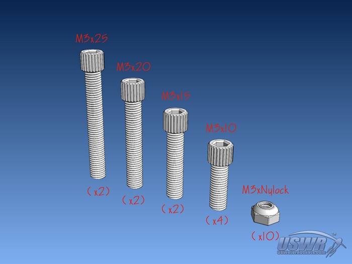
In addition to the printed parts you will need to get a few screws and things to hold the print together. The fasteners used are:
| Part | Quantity | Used For |
| M3x25 Socket Cap Screw | 2 | Ankle Joints on Feet |
| M3x20 Socket Cap Screw | 2 | Shoulder Pivot Joints |
| M3x15 Socket Cap Screw | 2 | Leg Retract Top Cover |
| M3x10 Socket Cap Screw | 4 | Neck Ring attachments |
| M3 Nuts (Nylock type preferred) | 10 | For the screws above |
| 1.75mm Filament | 1 | Used for alignment pins in many glue joints, and as Battery Hoses. |
Note: Some of the assembly requires gluing pieces together. Glue appropriate for the type of plastic you have used for your prints will be needed. We suggest a good epoxy or CA Glue. Most of the glue joints in this design use alignment pins which you will cut from scrap 1.75mm filament, so have some extra filament handy.

Gallery


Part 1: Left and Right Leg Assemblies
Step 1:
Glue one Leg_Outer to the Left_Leg_Inner, cutting alignment pins from the 1.75mm filament piece and inserting them into the holes on the mating surfaces of the joint for alignment.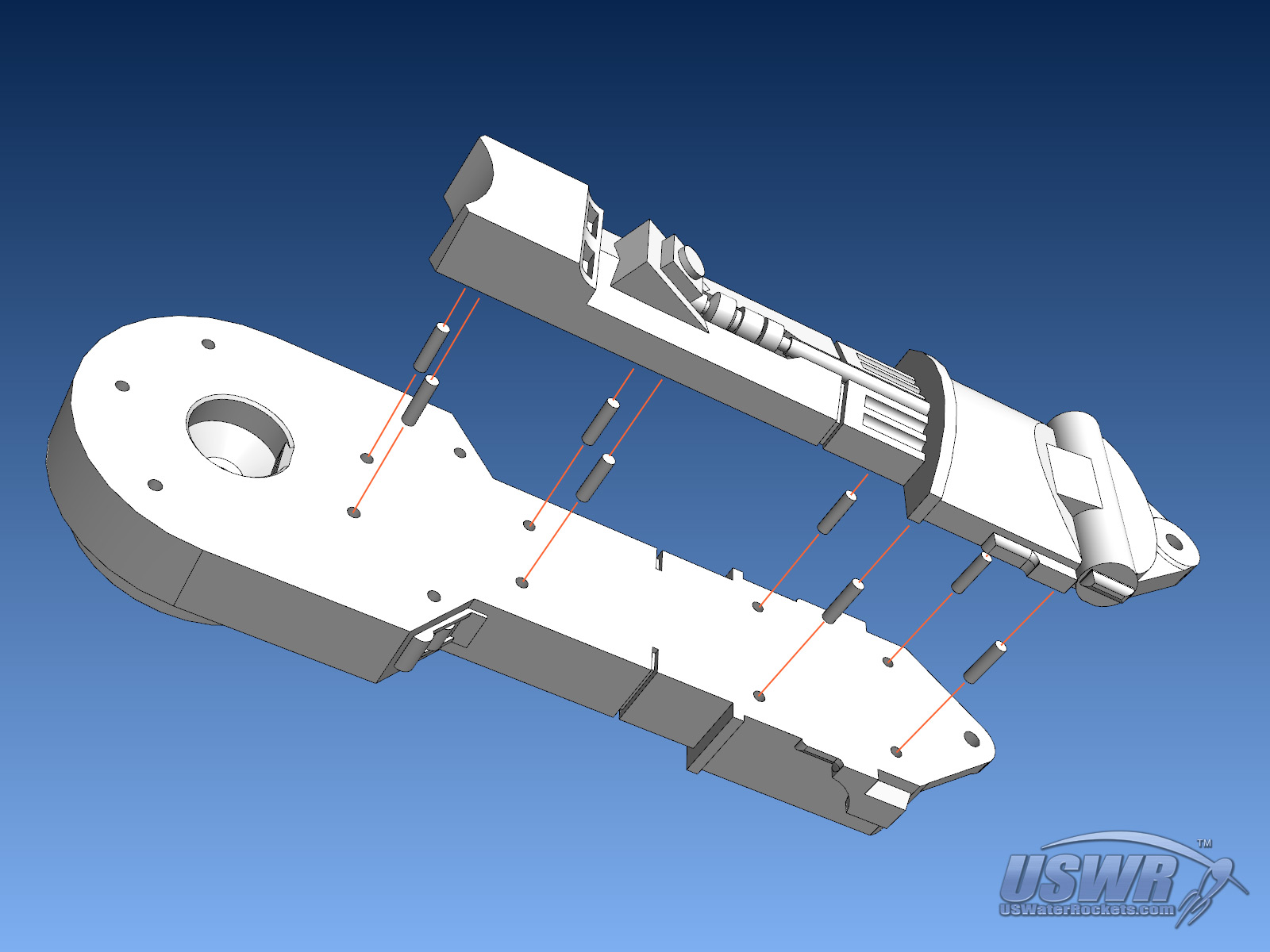
Step 2:
Glue the Left _Shoulder to the Left_Leg_Inner. Note that the shoulders have details which are specific to the left and right sides, so do not swap them if you want perfect accuracy of the droid. The Shoulder Button detail should be located toward the front side of the legs. .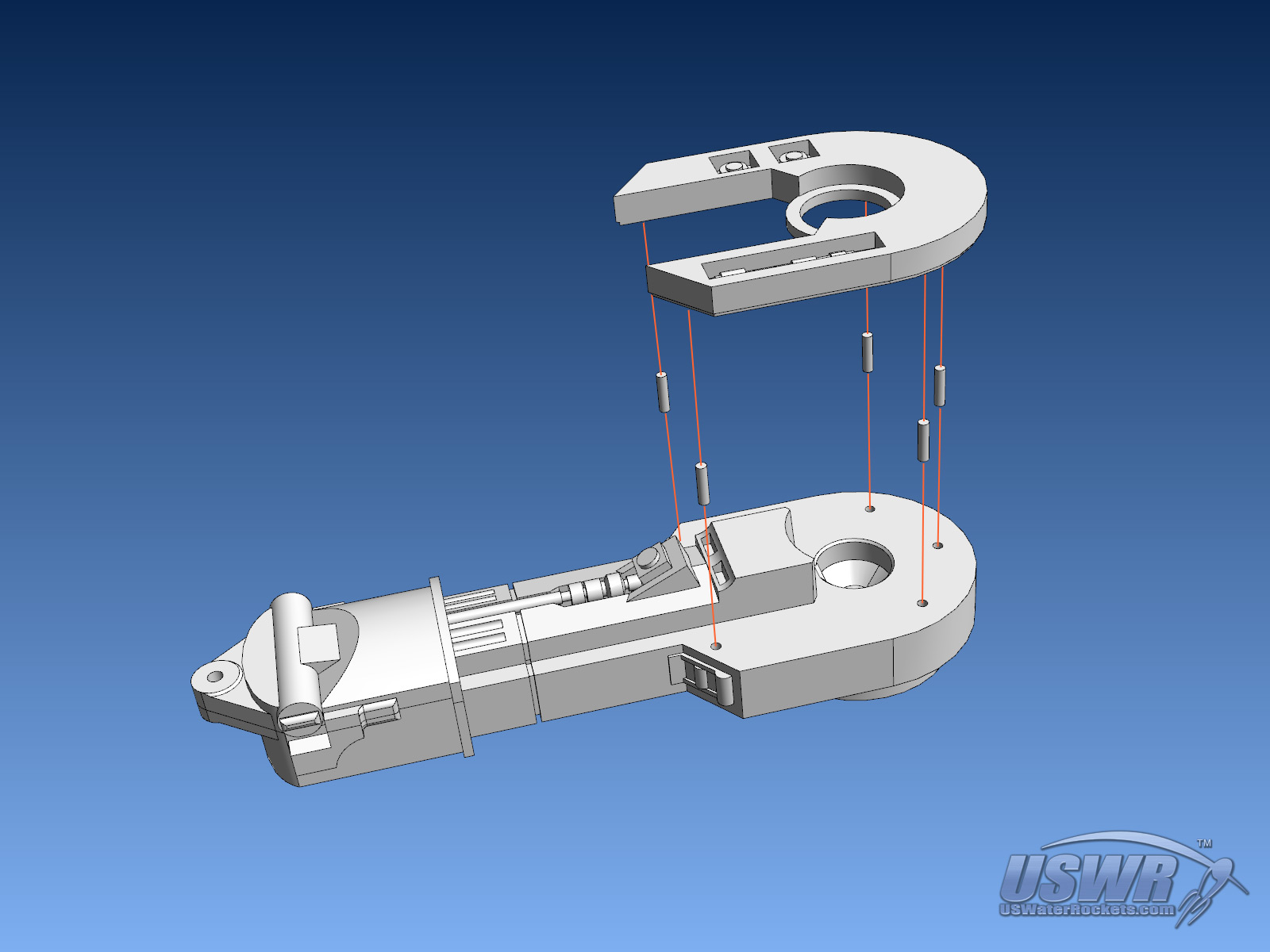
Step 3:
Insert an M3 nut through the channel cut in the top of the Left_Foot, and slide the nut into the hexagonal cavity in the foot.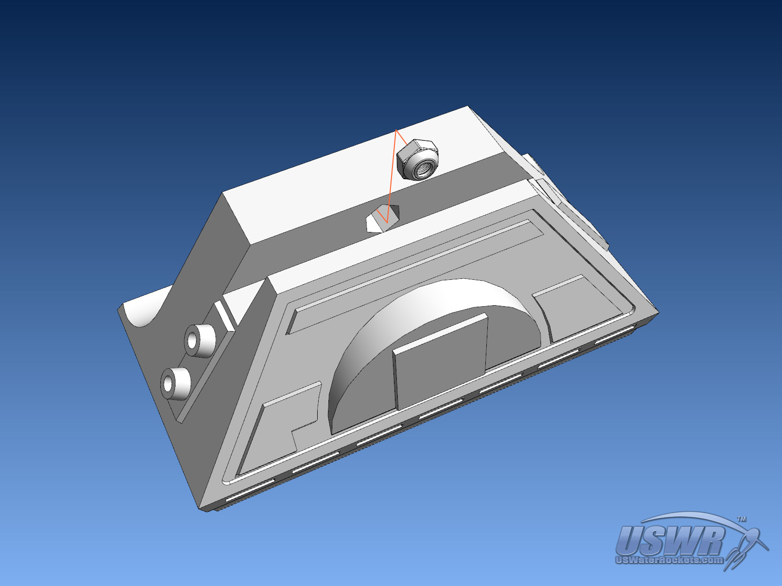
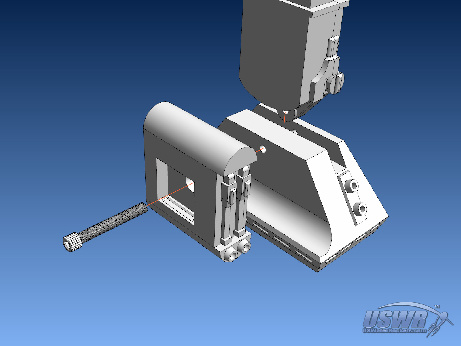
Step 4:
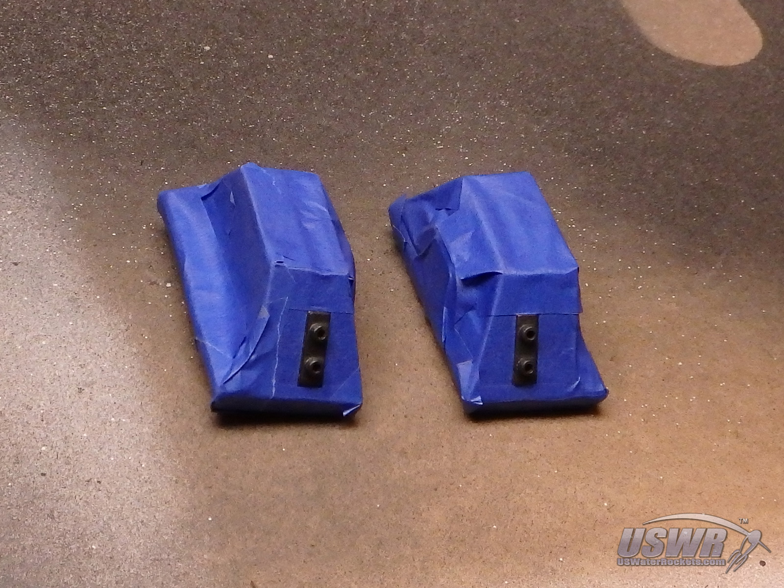
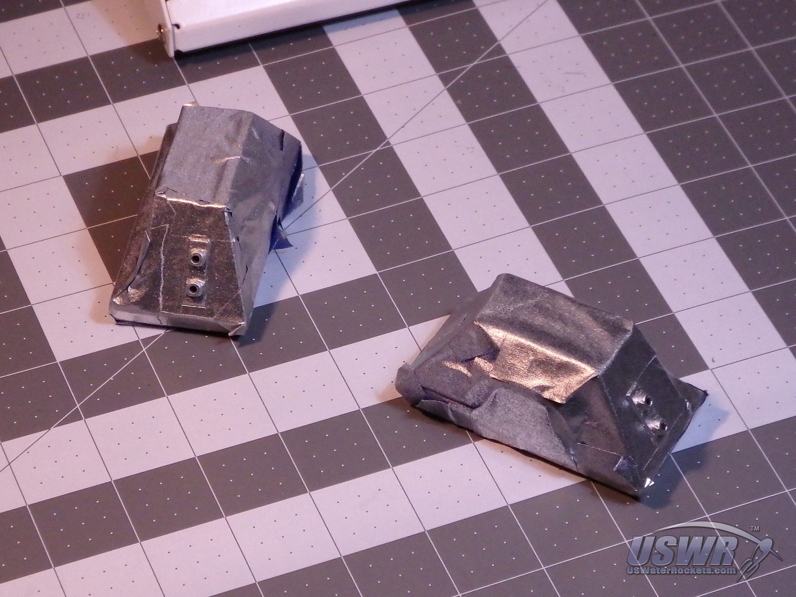
Insert a 25mm M3 Socket Cap Screw into the hole in the Left_Battery_Box, then through the hole in the inboard side of the Left_Foot. Get the screw to begin threading into the M3 Nut inside the foot. Slide the partially assembled Left_Leg into the channel in the top of the Left_Foot, and tighten the screw inside the Left_Battery_Box so it passes through the pivot hole in the bottom of the leg. Tighten the screw until it pulls the Left_Battery_Box tight to the Left_Foot.Gallery
Step 5:
Snap the Left_Battery_Door over the screw in the Left_Battery_Box. Press hard until it snaps in.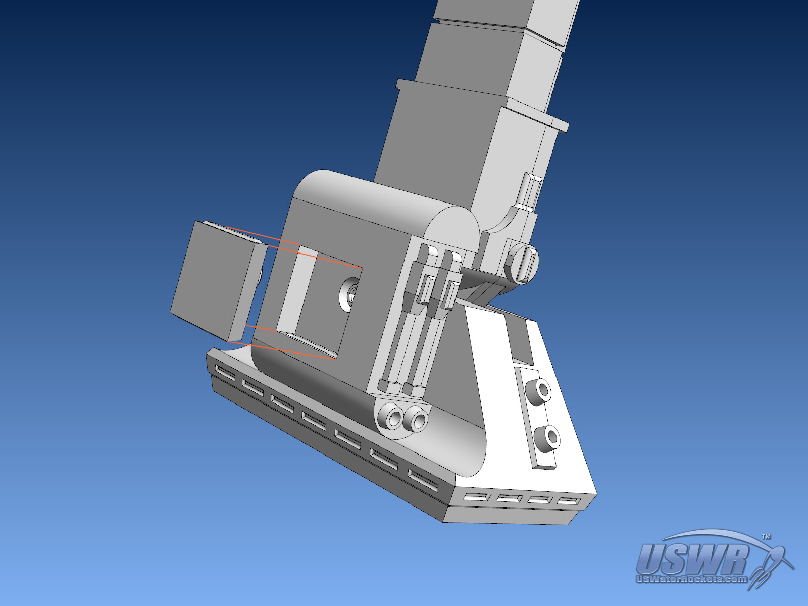
Step 6:
Using spare 1.75,, filament, create the two Battery Hoses that run from the Left_Battery_Box to the Left_Foot. Cut and bend the filament to fit, apply glue and insert into each hole.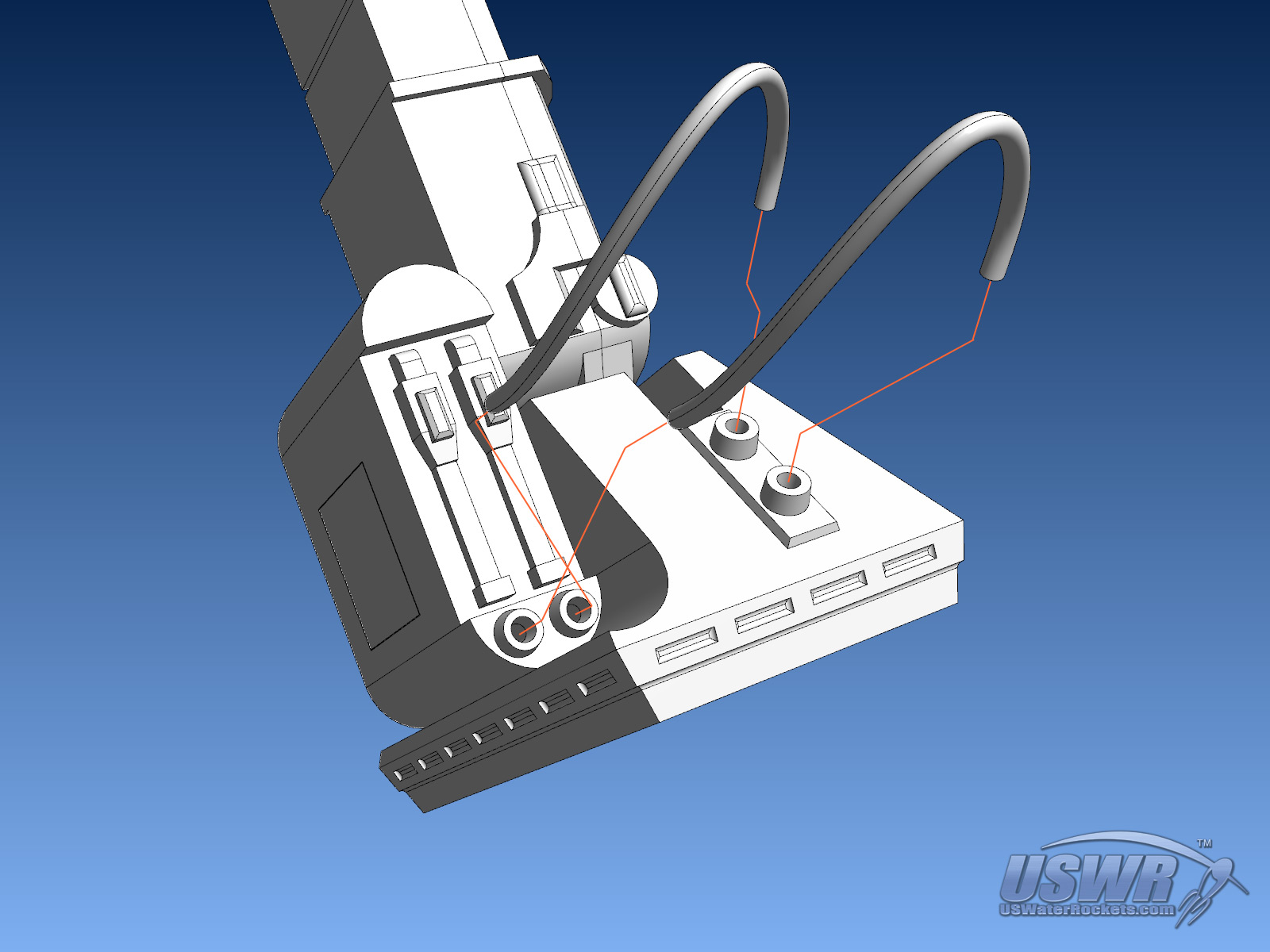
Step 7:
The Left Leg is now fully assembled. Repeat steps 1 through 7 for the Right Leg assembly. The completed Right Leg assembly should be a mirror of the Left Leg assembly.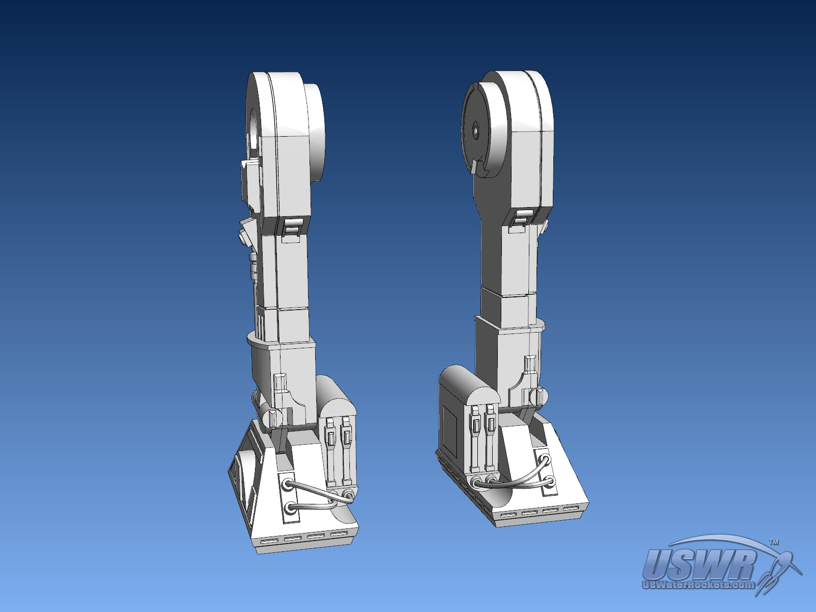
Part 2: Assembly of the Center Foot and Retraction Mechanism.
Step 1:
Glue the two Center_Leg_Half parts together, using more cut 1.75mm filament pins for alignment.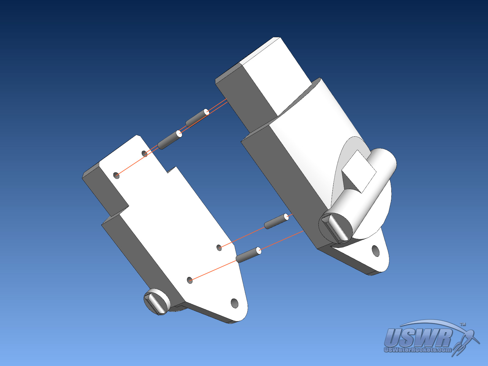
Step 2:
Snap the Center_Foot on the bottom of the assembled Center_Leg. The two bumps on the bottom of the Center_Leg will engage into holes in the sides of the channel on top of the Left_Foot and become a pivoting joint.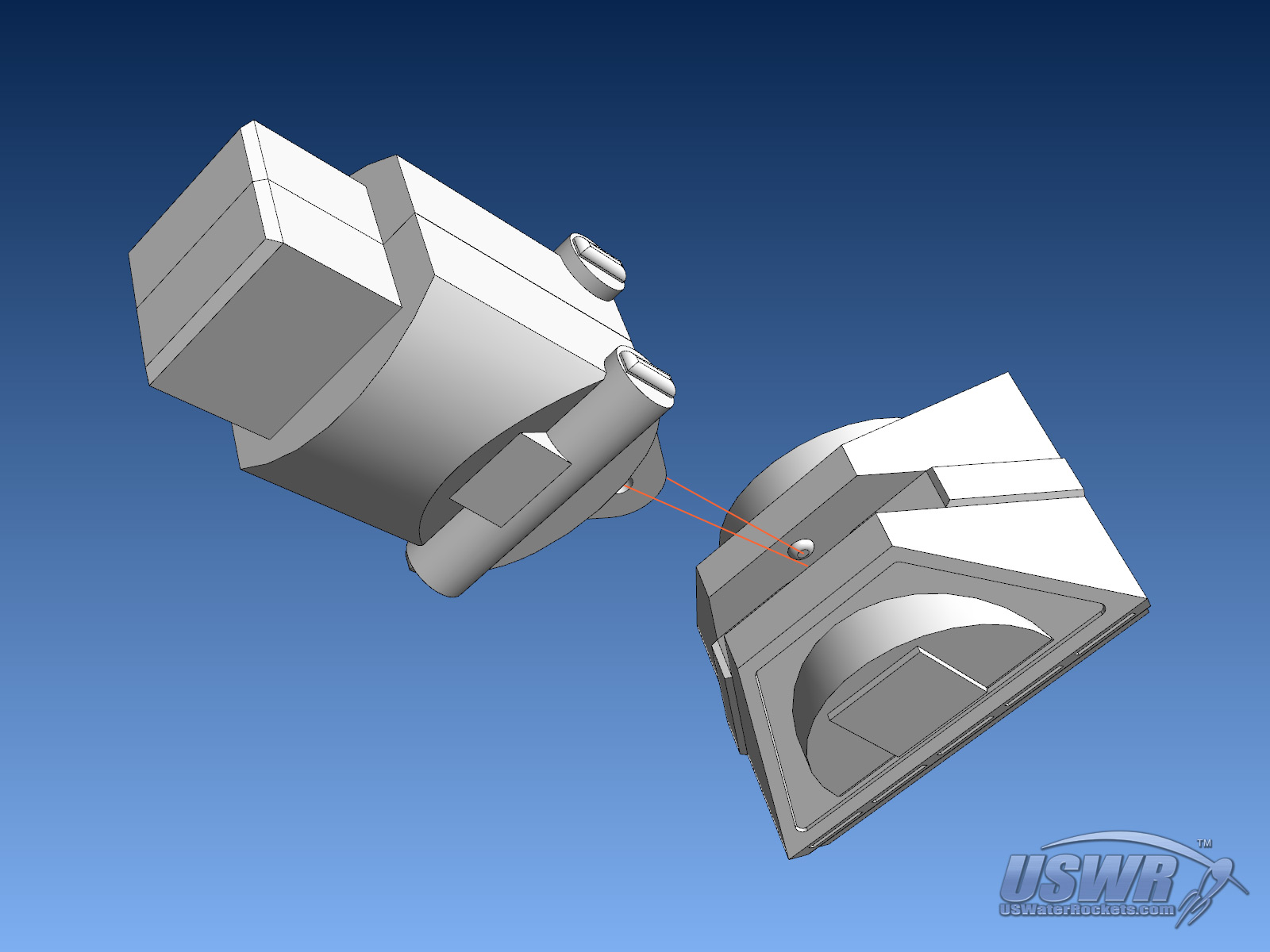
Step 3:
Slide the Center_Leg_Slider into the Center_Retract_Track. The side with the cutouts for the Center_Leg faces the rectangular side of the Center_Retract_Track. Work the slider up and down to make sure it slides easily.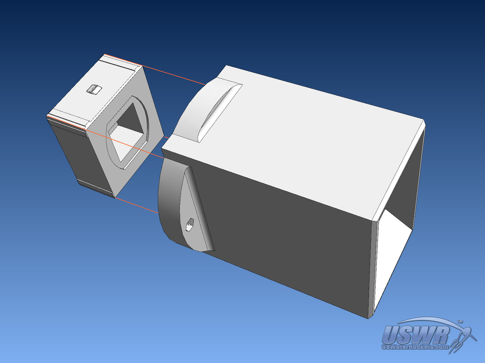
Step 4:
Use two M3x10 socket cap screws and M3 nuts to attach the Center_Retract_Top to the Center_Retract_Track..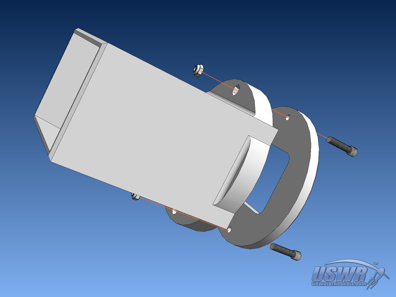
Step 5:
Glue the Center Leg assembly into the opening in the Center_Retract_Slider. These parts are symmetrical, so don't worry about which side is the front or back.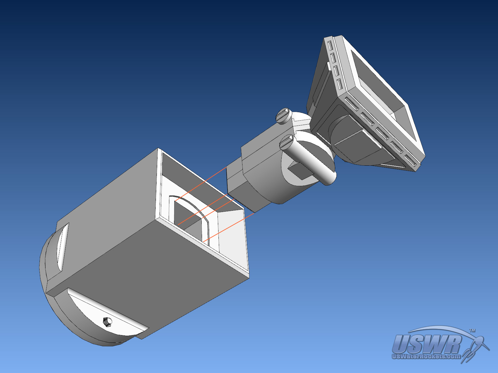
Step 6:
Glue the Skirt onto the rectangular end of the Center_Retract_Track.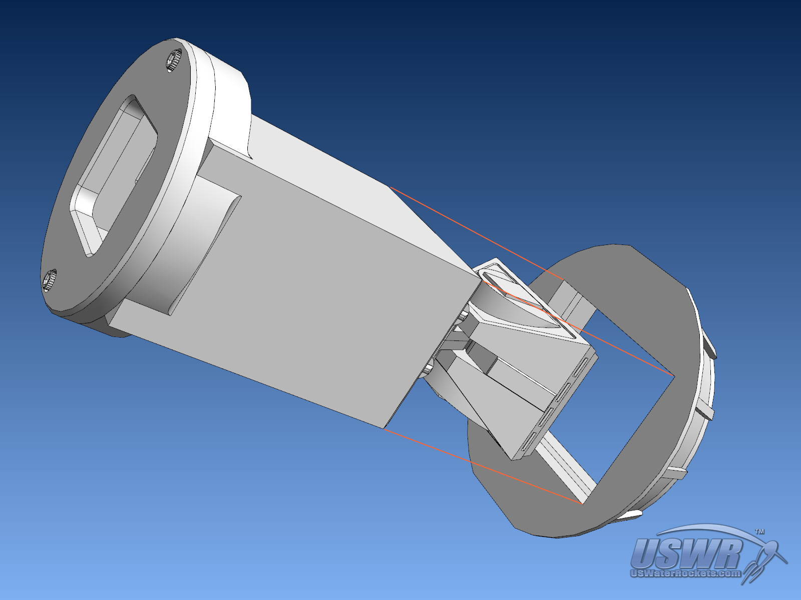
Part 3: The Torso:
Step 1:
Glue the two Octagon_Ports to the cutouts in the lower Torso.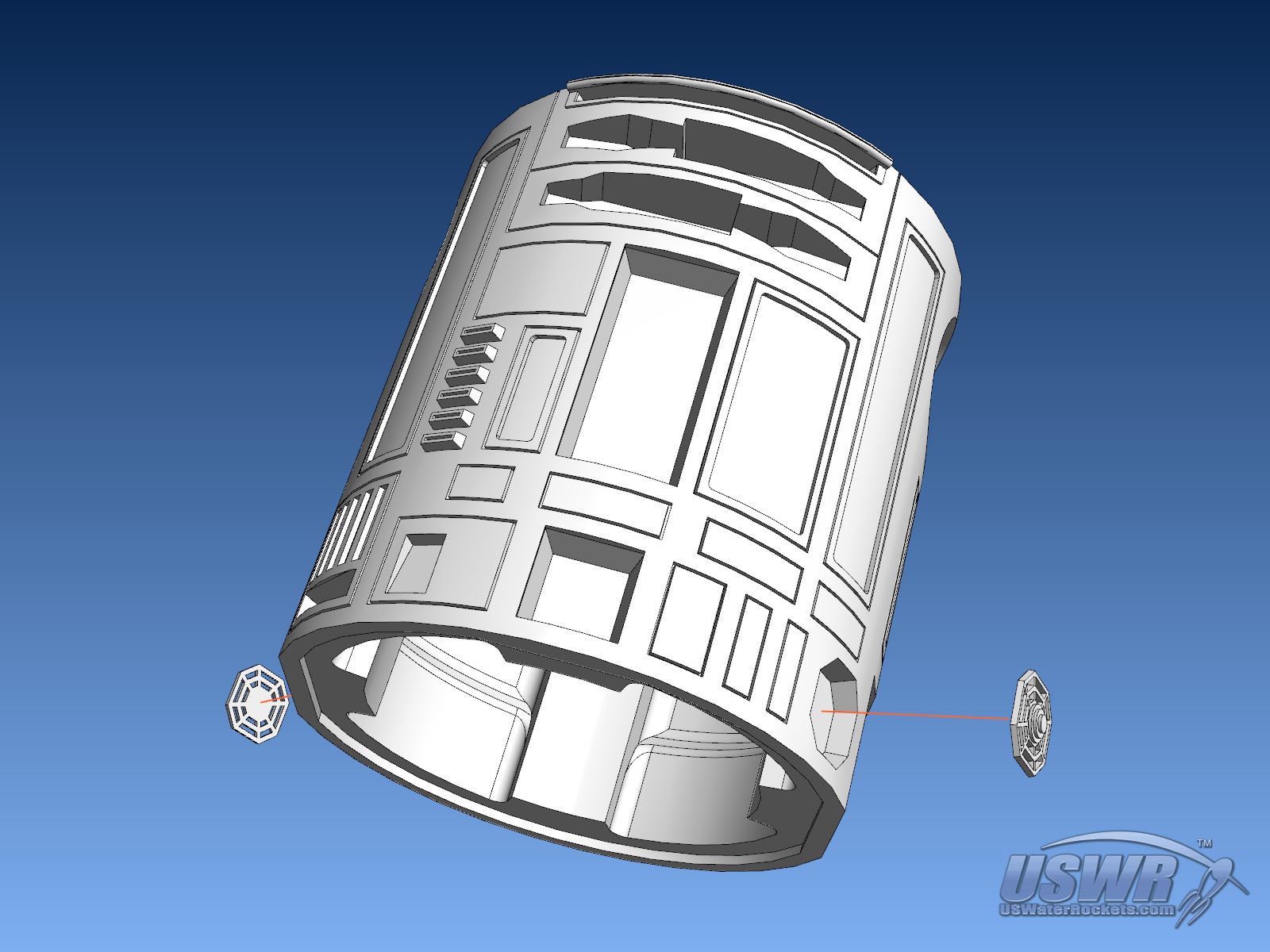
Step 2:
Glue the two Power_Coulplings into the cutouts in the lower Torso.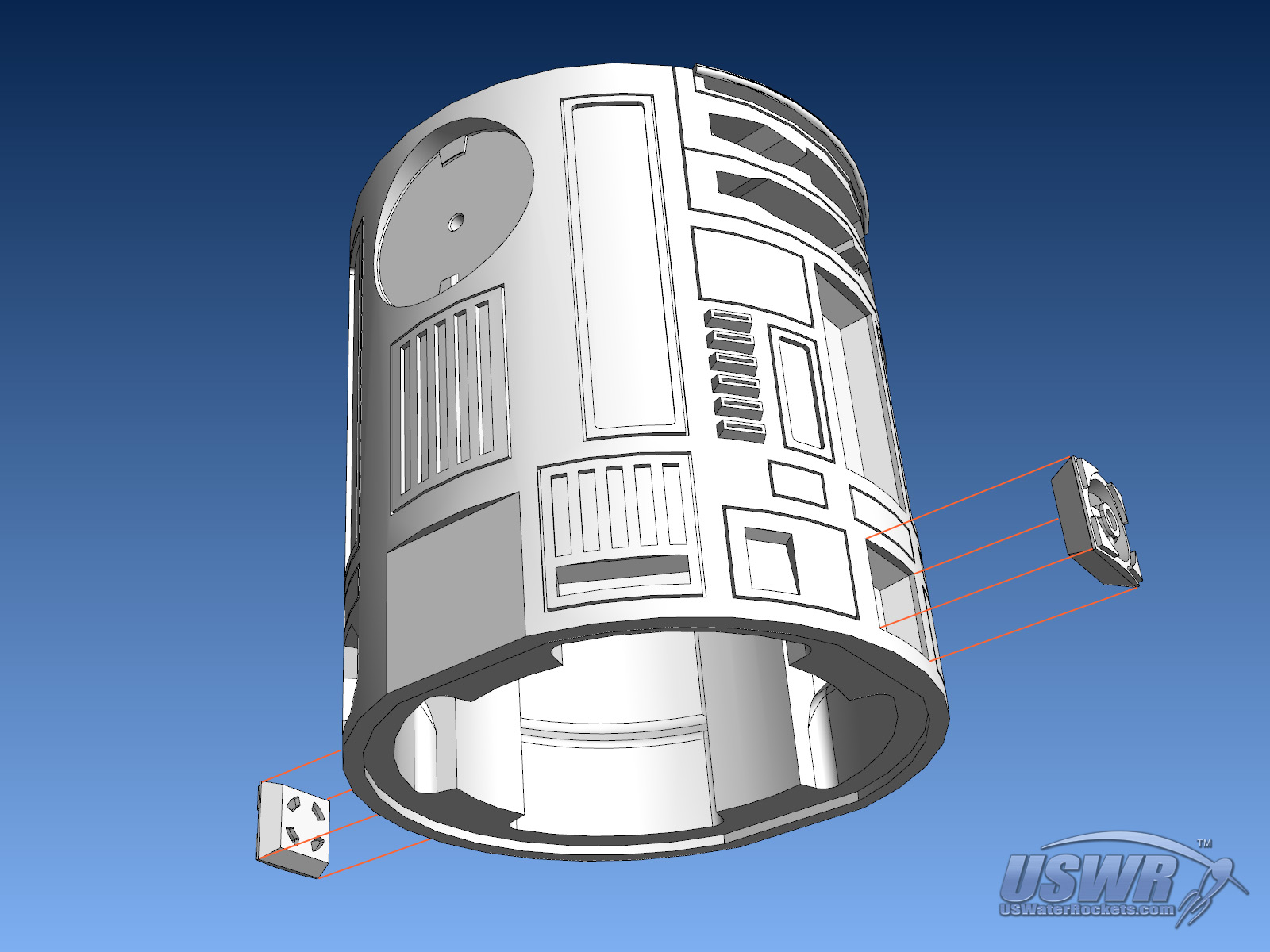
Step 3:
Glue the two Utility_Arms to the cutouts in the upper front of the Torso, using 1.75mm pins for alignment.
Step 4:
Glue the Center_Vent into the cutout in the front of the Torso.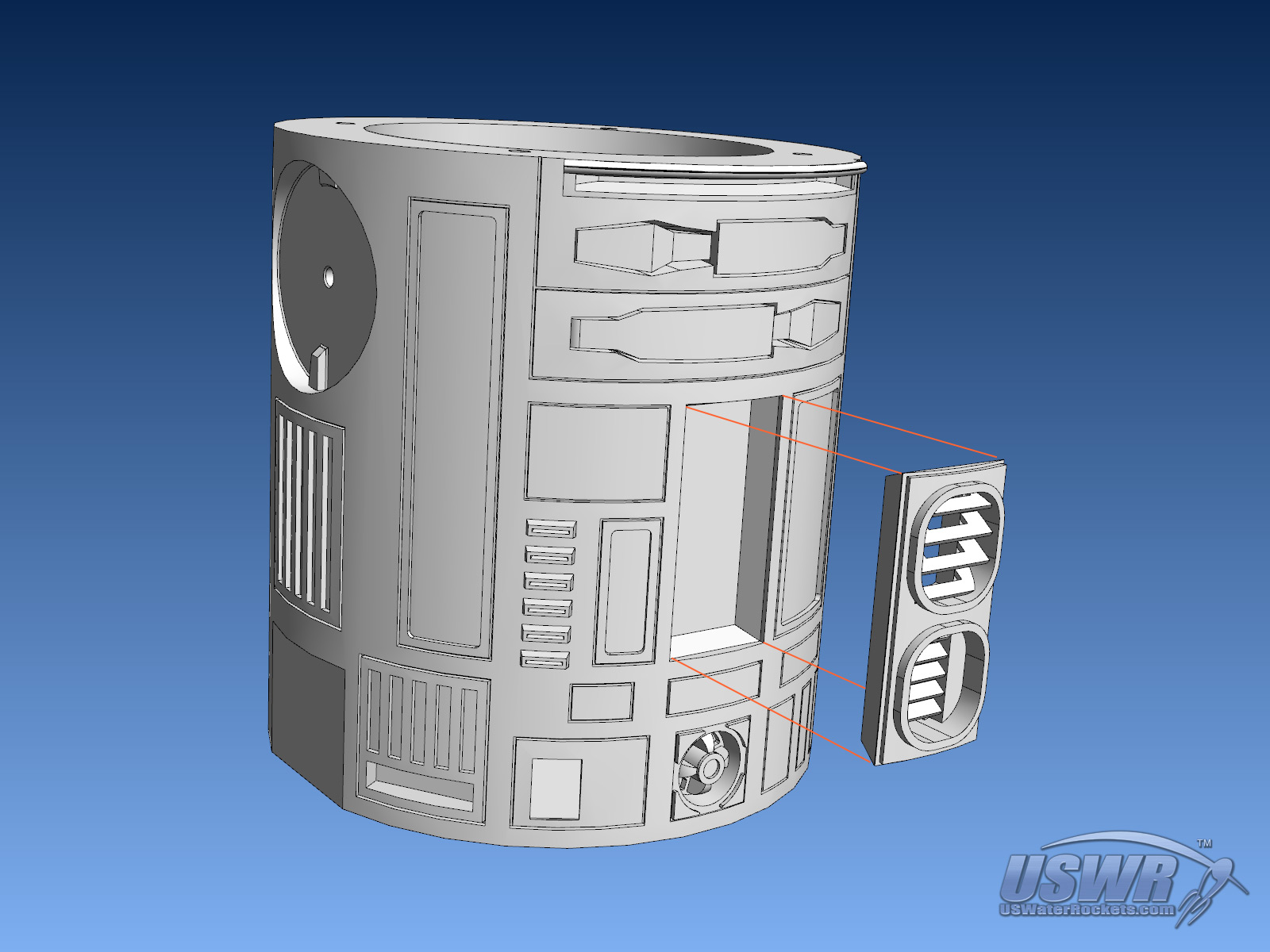
Part 4: The Dome:
Step 1:
Glue the three Holoprojectors into the circular cutouts in the Dome. The projectors can be rotated before the glue sets to produce a desired pointing position.
Step 2:
Glue the Radar_Eye into the cutout in the front of the Dome.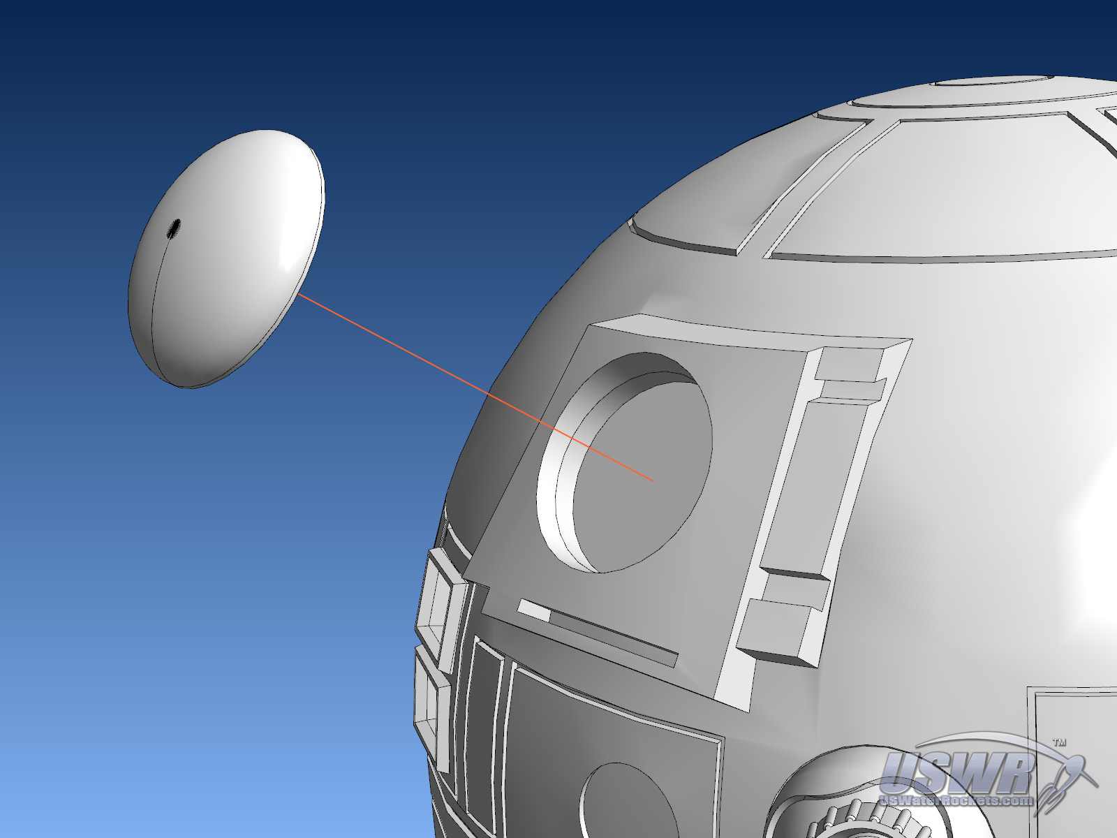
Part 5: Final Assembly:
Step 1:
Push four M3 nuts into the hexagonal cutouts under the top lip inside the torso. They should snap in place and be held captive so they don't fall out or need a wrench to tighten.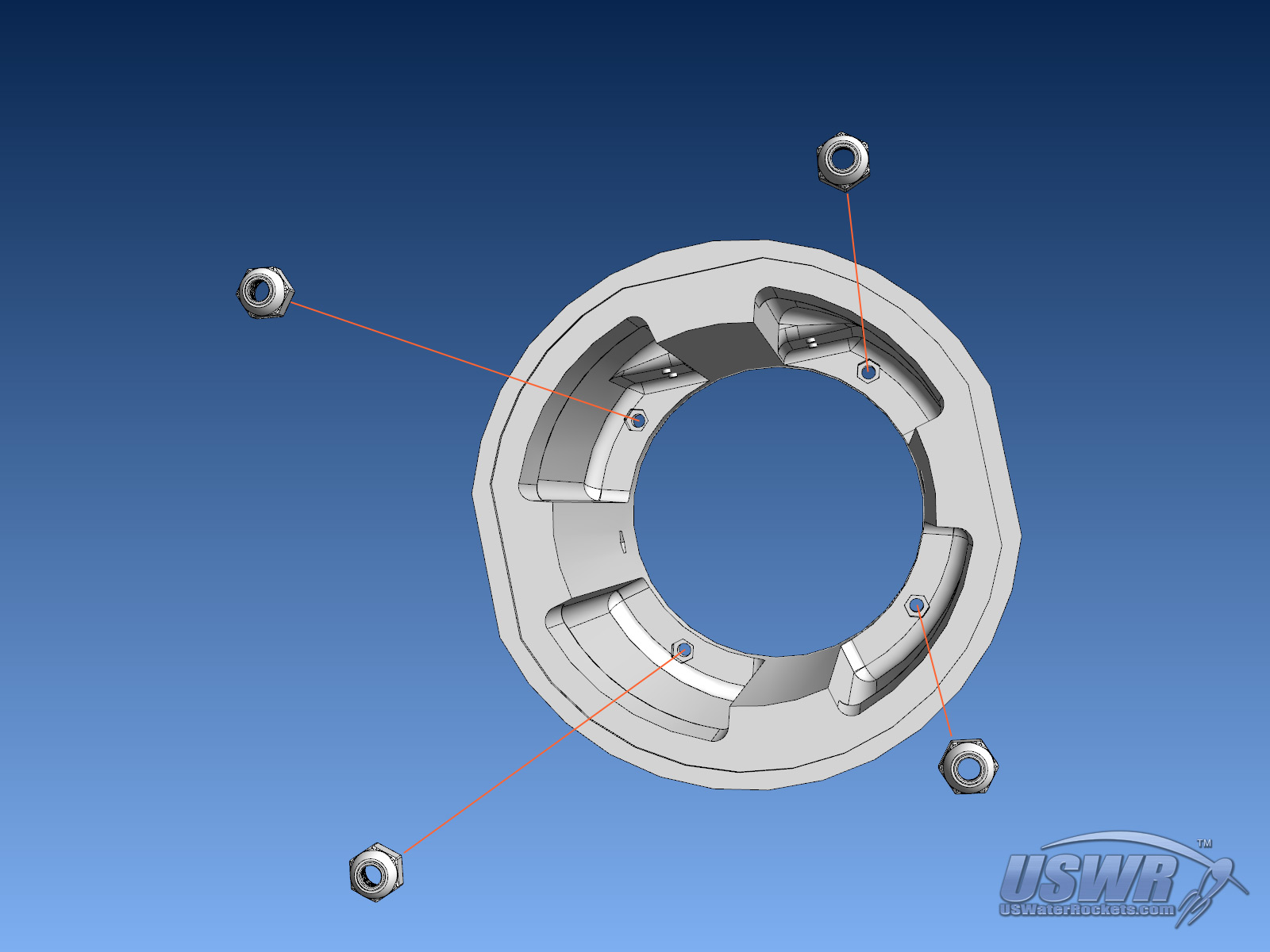
Step 2:
Use four M3x10 screws to attach the Neck_Ring to the top of the Torso.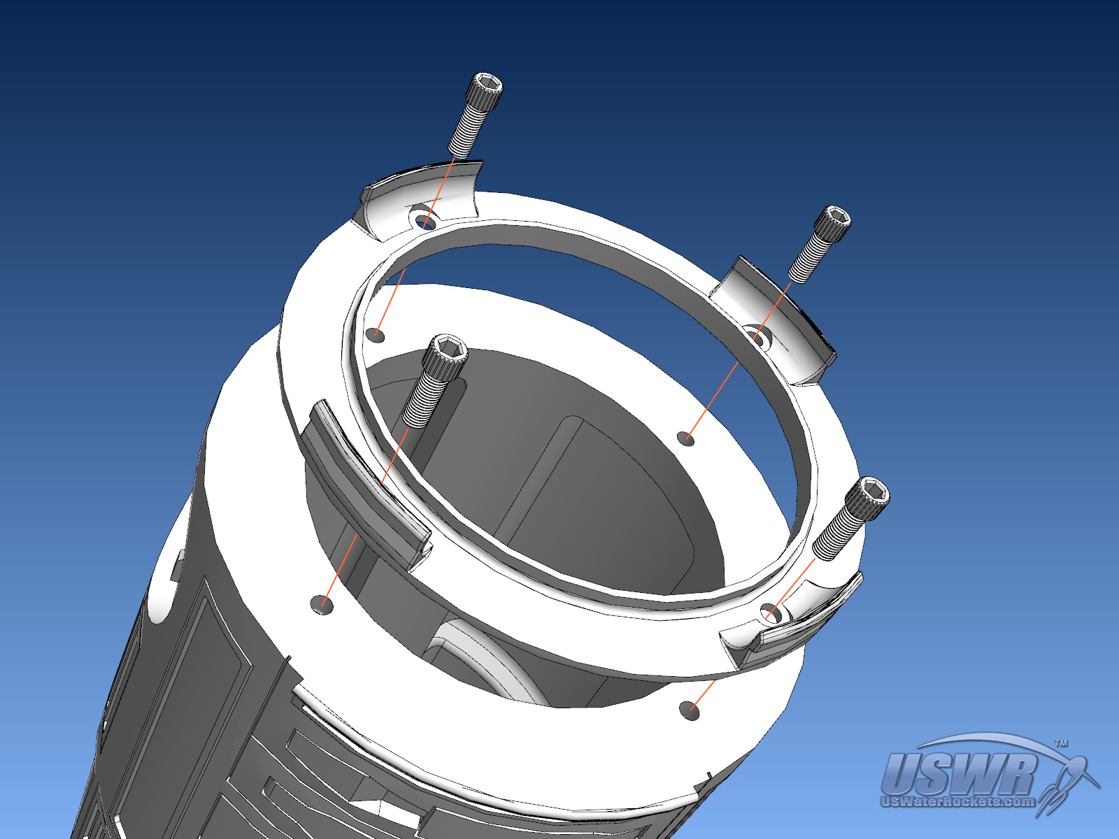
Step 3:
Push two M3 nuts into the Hexagonal cutouts inside the Torso at the pivot points where the legs attach on each side.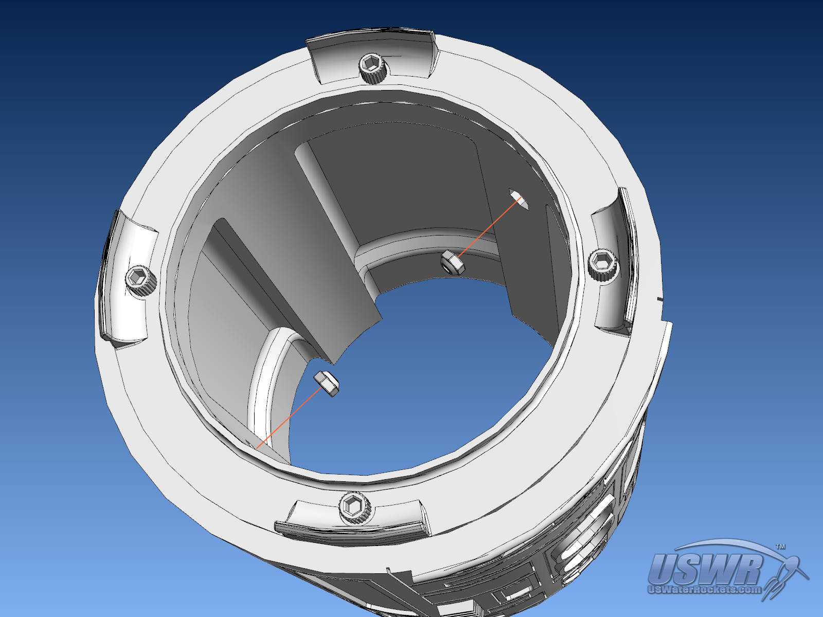
Step 4:
Use two M3x20 screws to secure the Left and Right Legs to the Torso. Do not overtighten the screws, otherwise the legs will not rotate at the shoulders.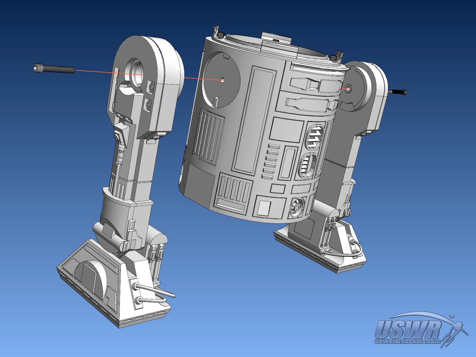
Step 5:
Snap the two Shoulder_Hubs into the holes in the Left and Right shoulders covering the screws holding the legs on. Do not glue the Shoulder_Hubs, so you can remove them later for maintenance on the shoulder screws.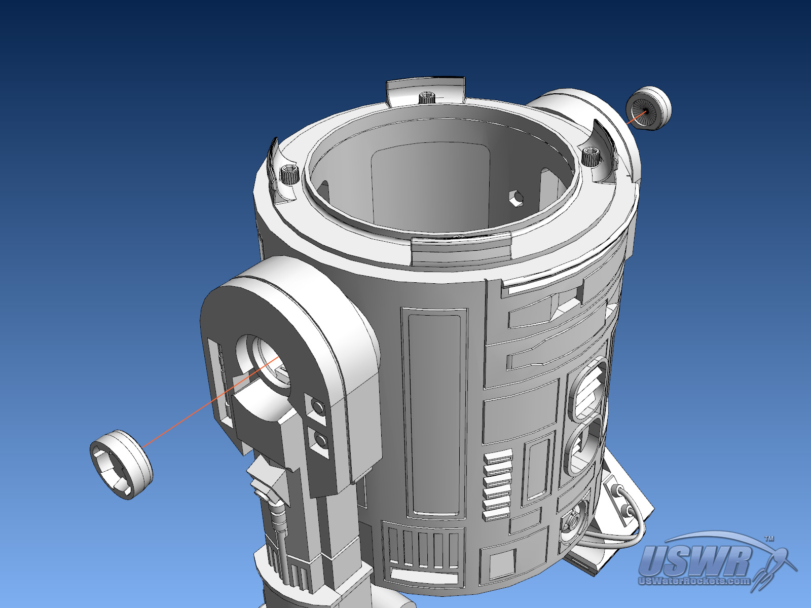
Step 6:
Slide the Center Leg assembly into the bottom of the Torso. The Skirt will snap into the bottom of the Torso at the perimeter. Do not glue this in place if you wish to be able to perform maintenance on the leg retraction slider mechanism.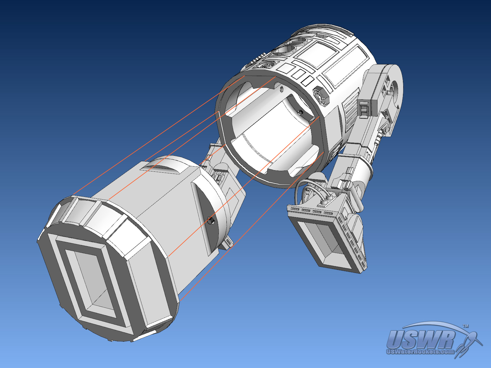
Step 7:
Push the Dome on top of the Neck_Ring, and it will snap in place.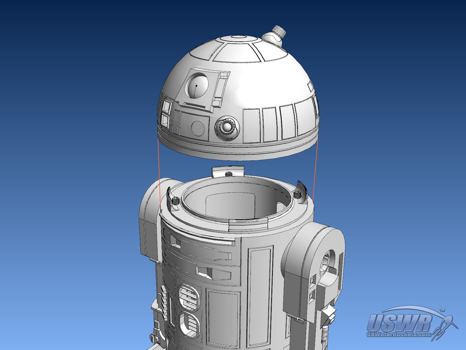
Congratulations! You're done!
Finished Droid Gallery


3D Printed Star Wars Droid Replica Video Tutorial:
 3D Printed Star Wars Droid Replica Tutorial by
U.S. Water Rockets is licensed under a Creative Commons Attribution-NonCommercial 3.0 Unported License.
3D Printed Star Wars Droid Replica Tutorial by
U.S. Water Rockets is licensed under a Creative Commons Attribution-NonCommercial 3.0 Unported License.